Control
I chose orientation control to ensure my readings were consistent regardless of floor friction or battery levels. I chose orientation over angular speed control because I wanted the robot to stop when it took TOF measurements. In Lab 6, I only did P control, but for this lab I opted for PI control so that I could close the steady-state error gap. I felt there was no need for a D term, as that helps slow the robot down if the P is high, but I didn’t set P too high since we want slow and controlled turns. The set_points were also not too far from the starting point so the robot wouldn’t gain that much speed. Without the D term, my robot did occasionally oscillate because of the I term and lack of a D term, but we are allowed to take our time to reach the set_point. We need TOF data at exact angles so settling time and number of oscillations don’t matter as much.
To implement the I term, I have an error_sum variable that adds the calculated error multiplied by dt (which is the time for each control loop iteration in seconds here). To deal with integrator windup, I clamp the sum by a maximum and minimum value, which are the maximum PWM value and the negative of it, respectively, multiplied by 4. This gives me more granularity, and initially I set Ki=0.25, so the max the error_sum*Ki can be is the max PWM value. I eventually tuned Ki=0.1.
I also included a new function that ensures the calculated error is between (-180,180] so that we go the shortest angular path to the set_point.

We will end the PID control and move to the next angle once the absolute error is within 0.5° of the set_point for 5 consecutive times. The imuIndex for the data array is returned so that the next call to the angular PID controller can save data where it left off.
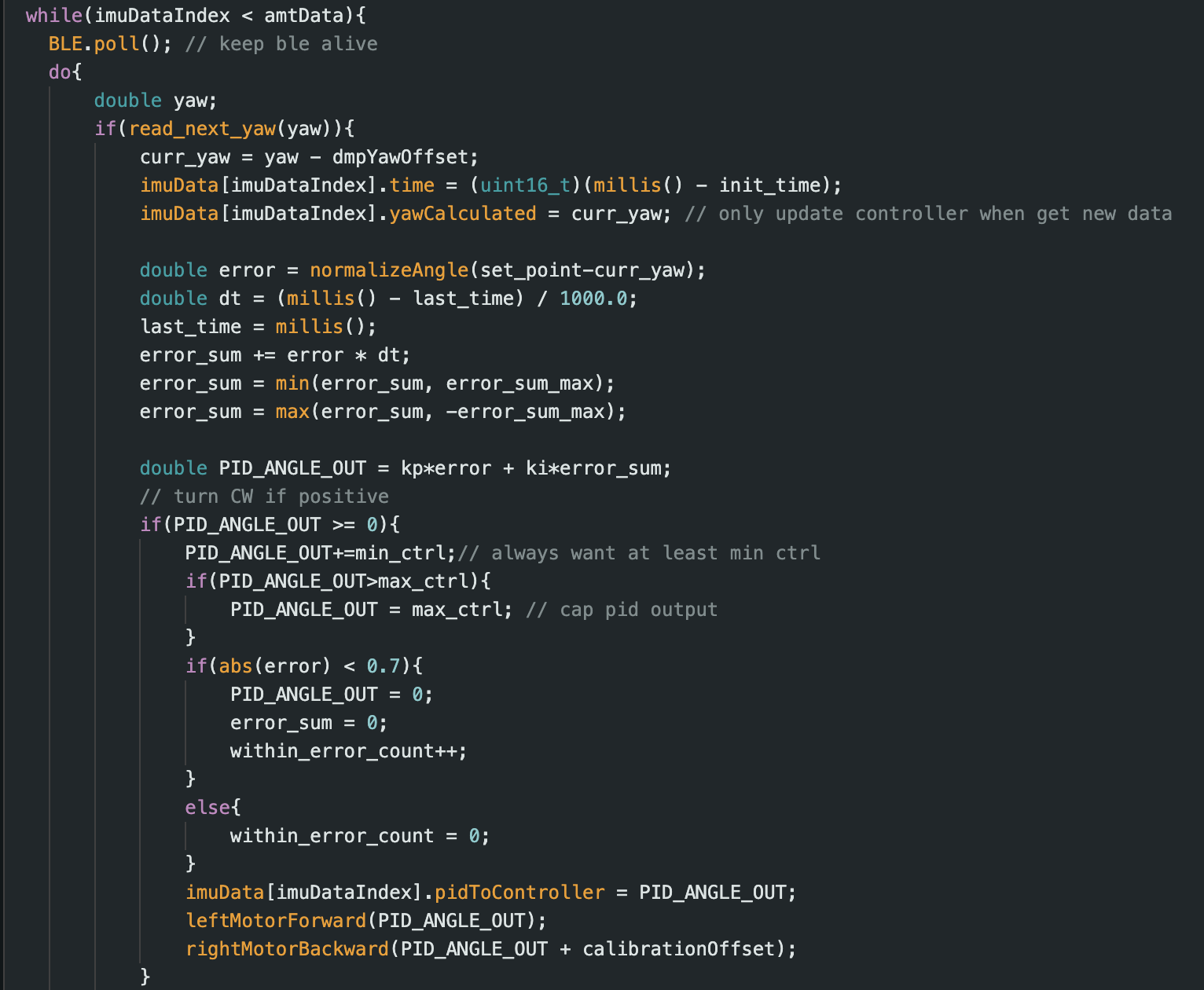
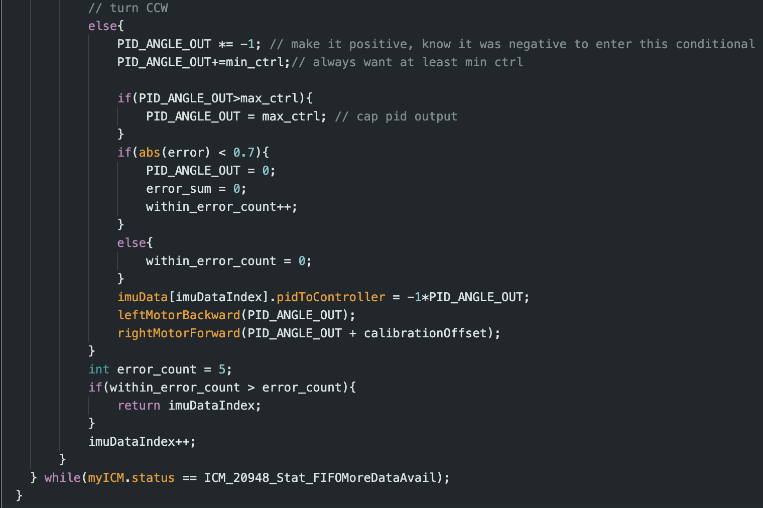
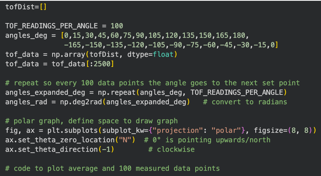
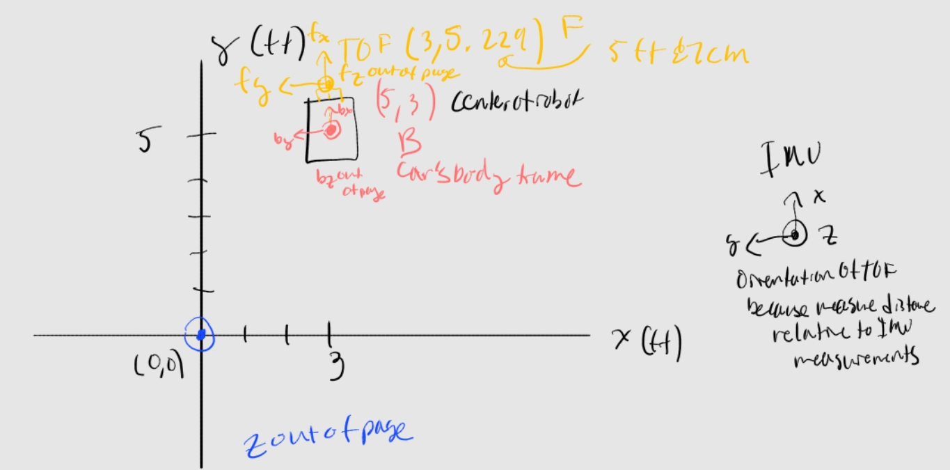
In my “.ino” script, I had a command that could edit the gains and set a flag so that the main loop knew to run a specific map code. I arrayed 25 readings, each spaced 15° apart, and the system uses PID control to reach the set points in order. Now the robot can do on-axis turns in small, accurate steps. After each set_point, before going to the next, the robot will stop in place and then gather 100 TOF data points using code from previous labs. We stop in place so the TOF sensor is guaranteed to read a fixed point in space.

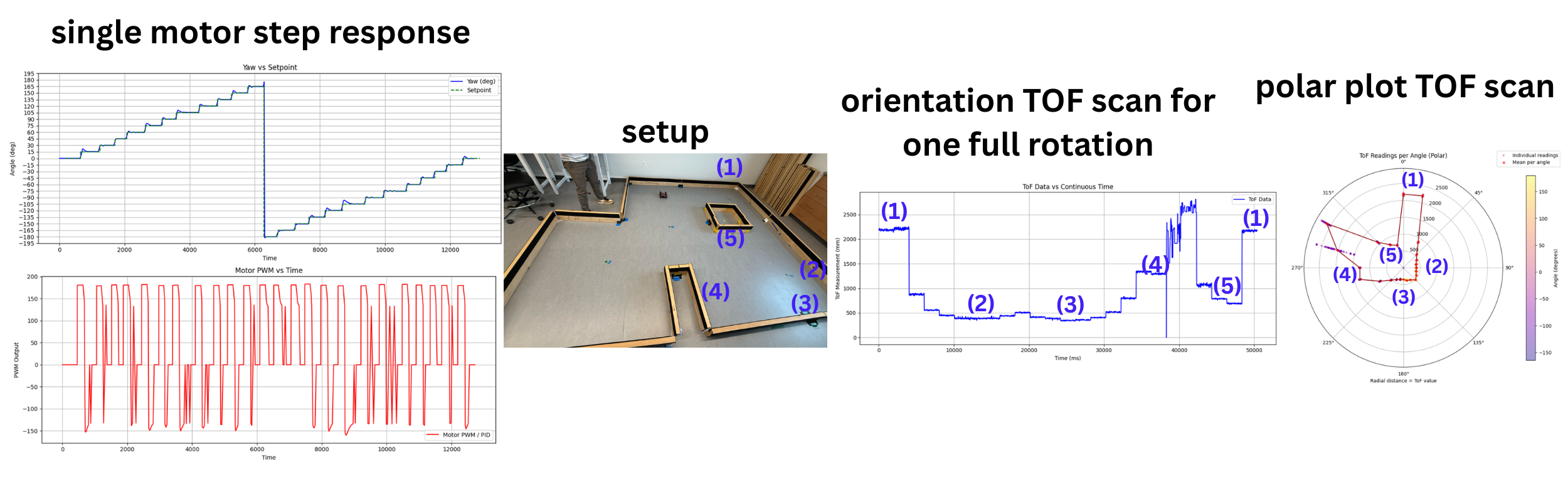
Video of the robot doing an on-axis turn reliably with graphs.
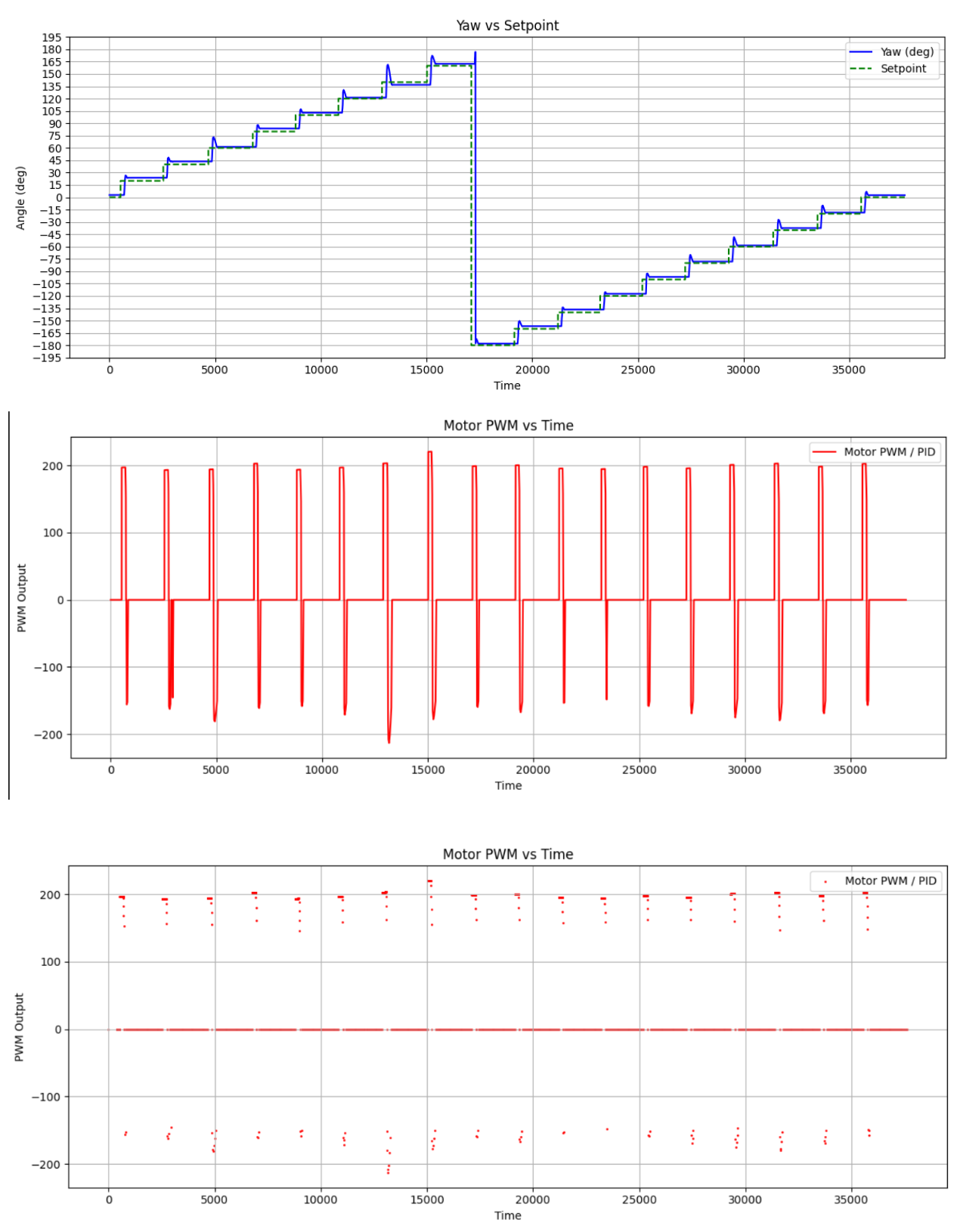
The time doesn't include the duration of TOF measurements when the robot is stopped. This trial was when I only had 19 set_points with 20-degree increments. Drift from the sensor is compensated by averaging 100 TOF measurements. My robot turns on axis fairly well; in future attempts, sometimes it ends with its center a bit behind where it was initially, but it is a negligible distance. The error in my angular PID is within 0.5°, and on average it is 0.2°. For a 4x4m square room (ignoring the distance of the TOF sensor to the center of the robot), the TOF sensor will read a maximum of 2sqrt(2)m (corner of wall). So lateral_errormax=2sqrt(2)*sin(0.5)=24.7mm and lateral_erroravg=2sqrt(2)*sin(0.2)=9.9mm. In lab 7 I found the STD to be 6.797178702320482mm. So on average the error is acceptable, but in the worst case we could run into some issues. Thus, I took 100 TOF measurements so we have enough data to average it out and have an acceptable error.
Reading out distances
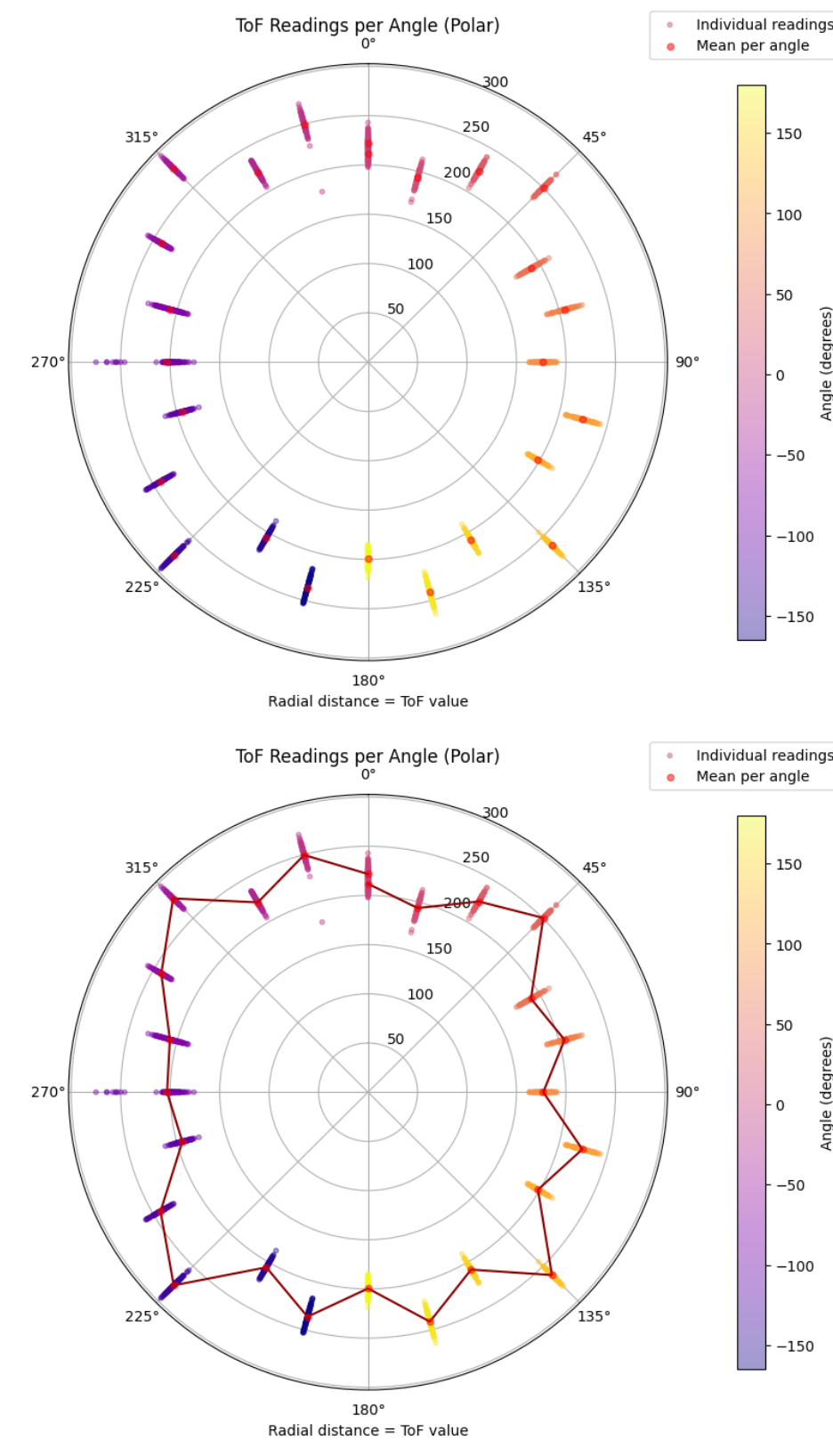
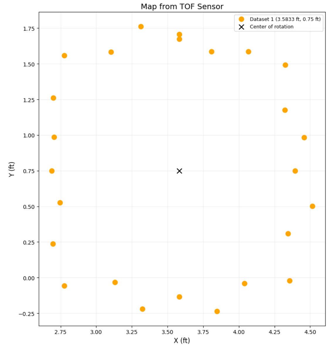
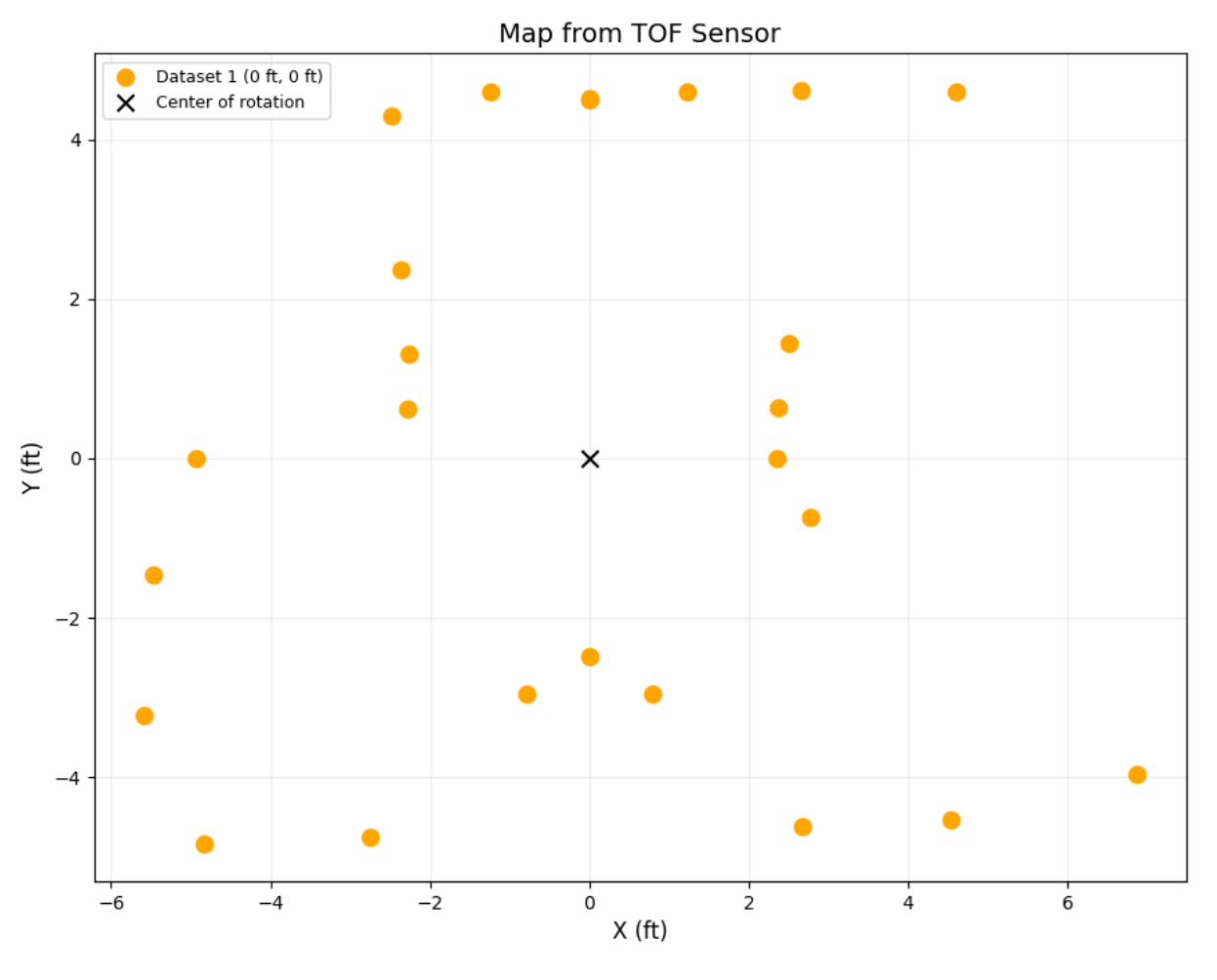
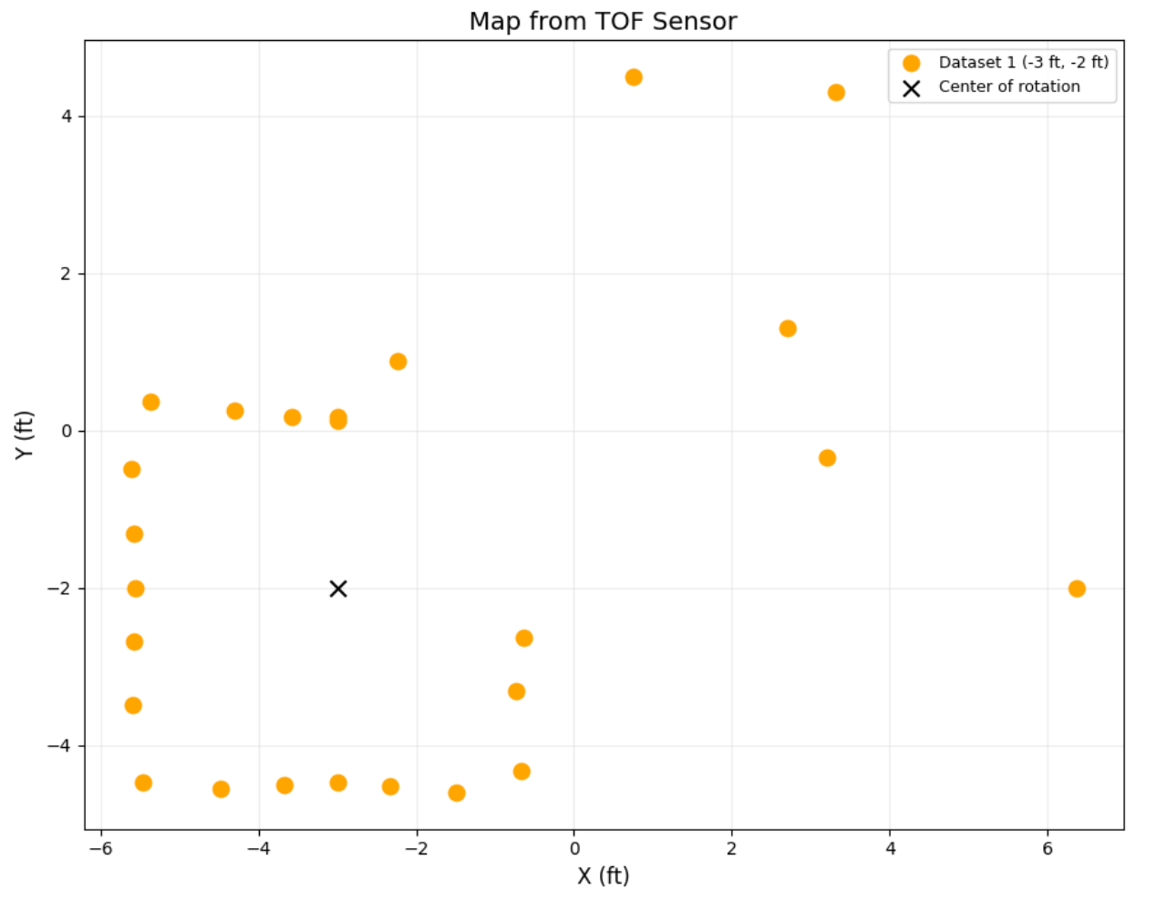
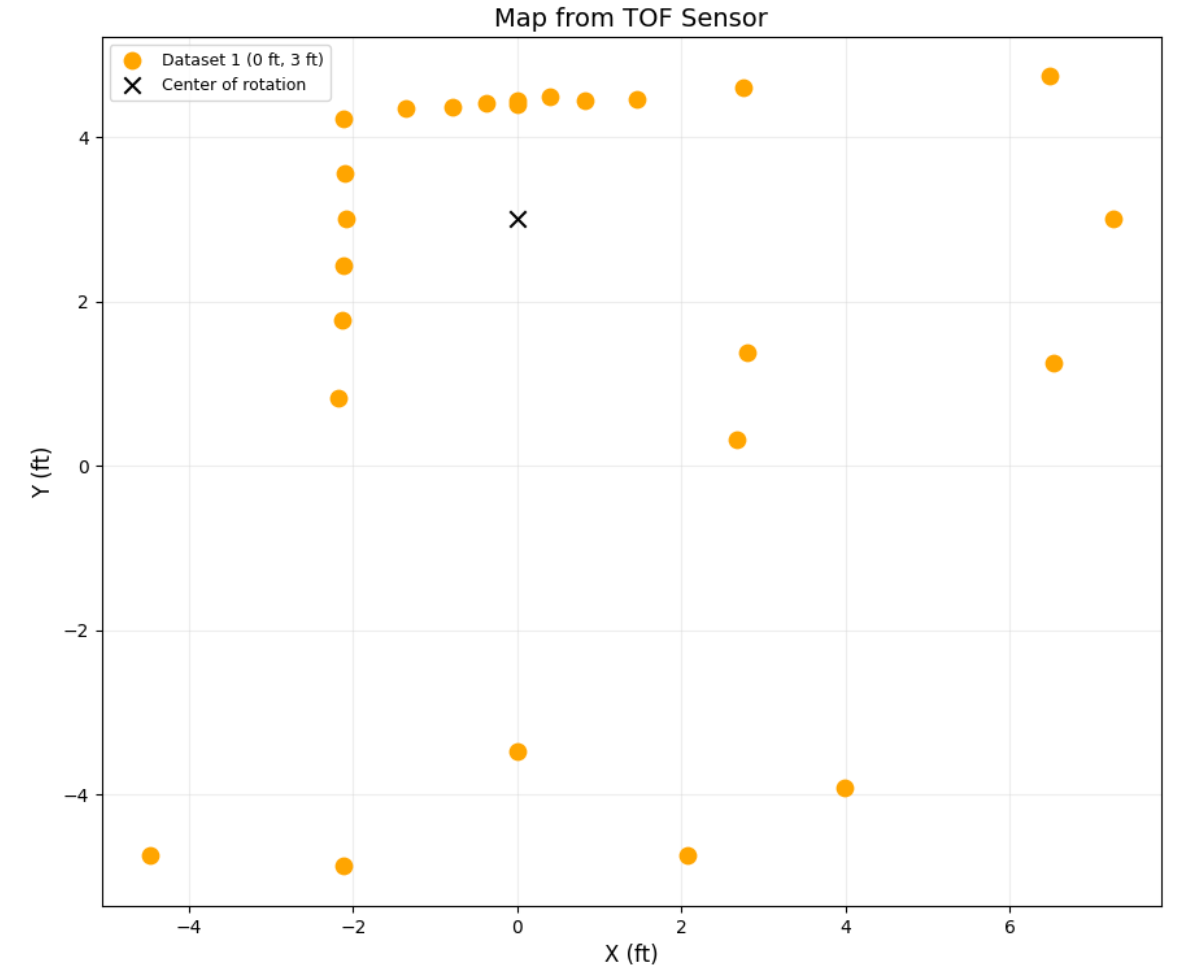
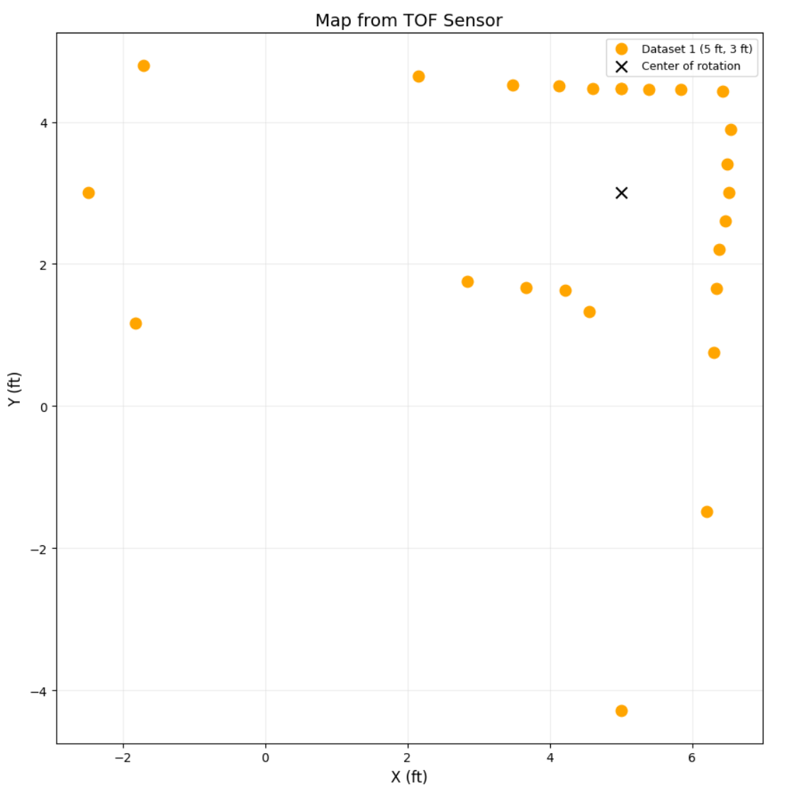
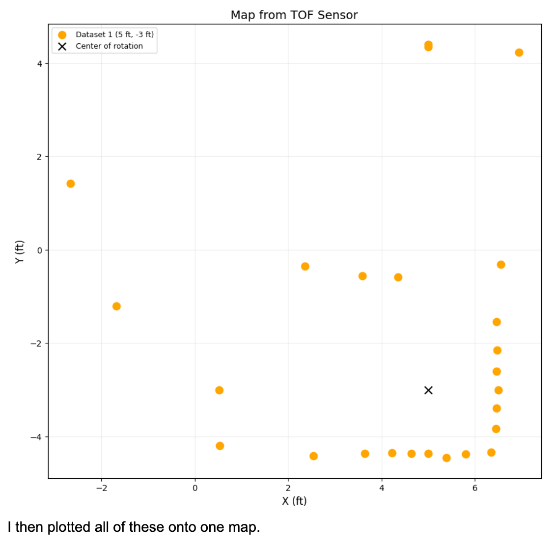
I execute my turn at (3.5833333333,0.75),(0,0),(-3,-2),(0,3),(5,3), and (5,-3)ft. I added the first point, in the center of the closed square, to get better information about that area. As I turn and then stop, I only use the front ToF sensor and, after all the data are collected, send them back to the Jupyter notebook over BLE. The robot is always in the same starting position where the front faces along the positive y-axis at 0° in the world frame. Because of how precise I made my controller, I assume the readings are equally spaced by 15°. To simplify things, I assume the robot turns in place, and comparing it to the map in real life, it matches up fairly well. For (5,3) below, rotating multiple different times got very similar results, proving the repeatability and precision.
(3.5833333333,0.75)
(0,0)
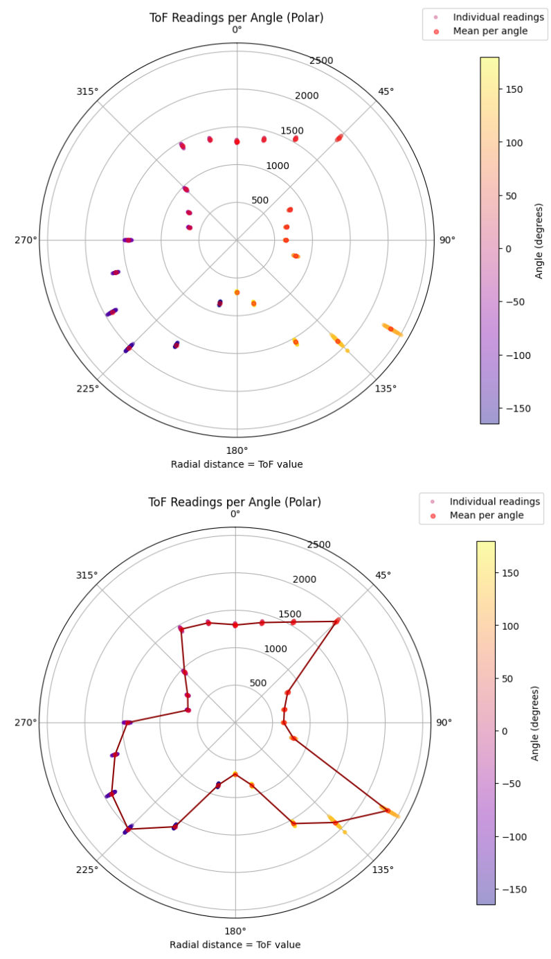
(-3,-2)
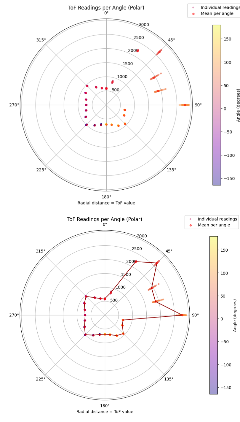
(0,3)
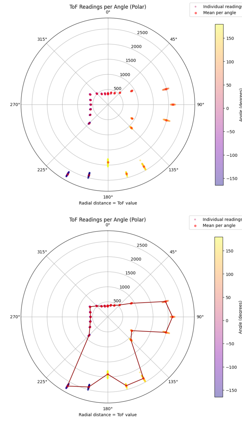
(5,3)
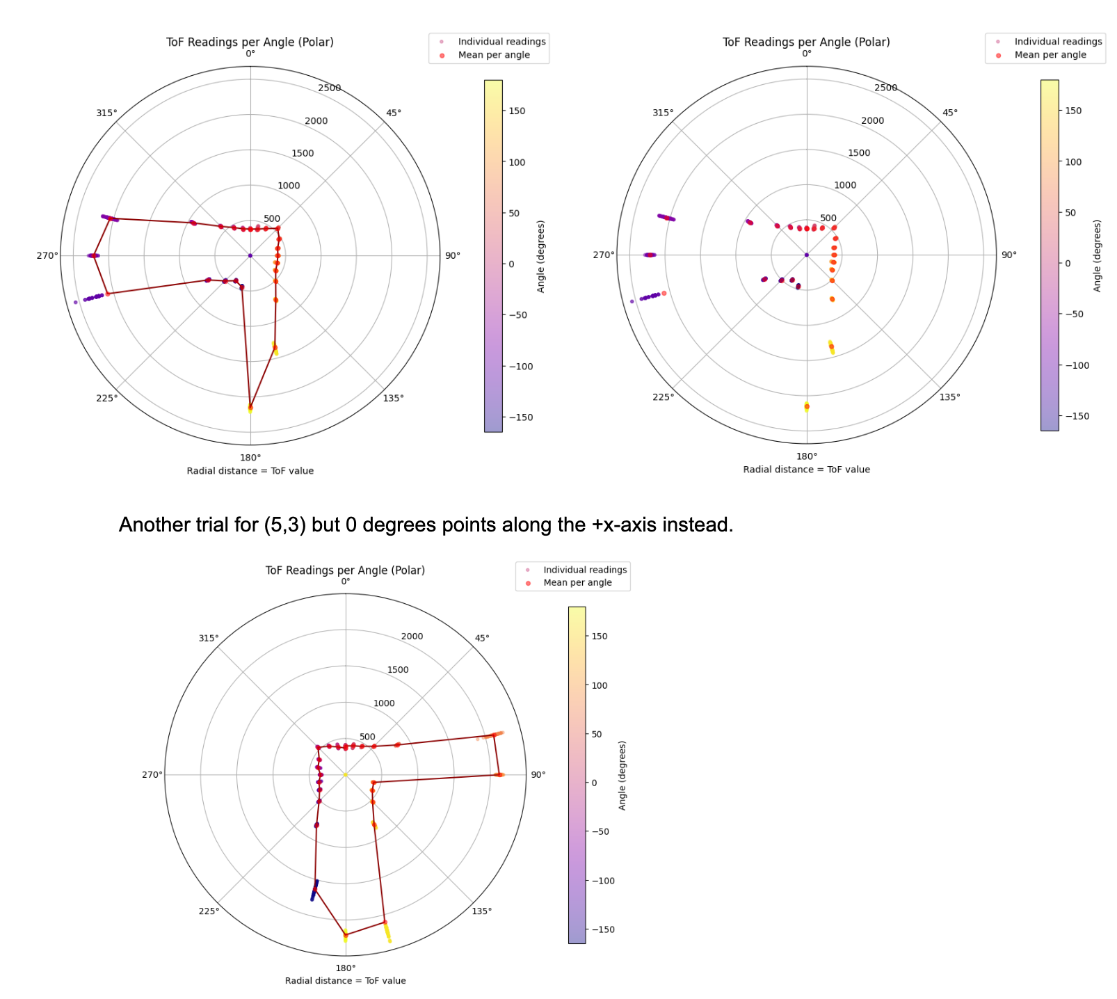
(5,-3)
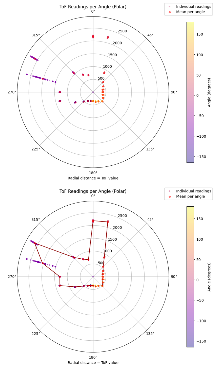
Basic implementation and I used Claude so it look prettier:
Orientation control for point (5,-3)ft with distance vs. time and in polar.
Merge and plot readings:
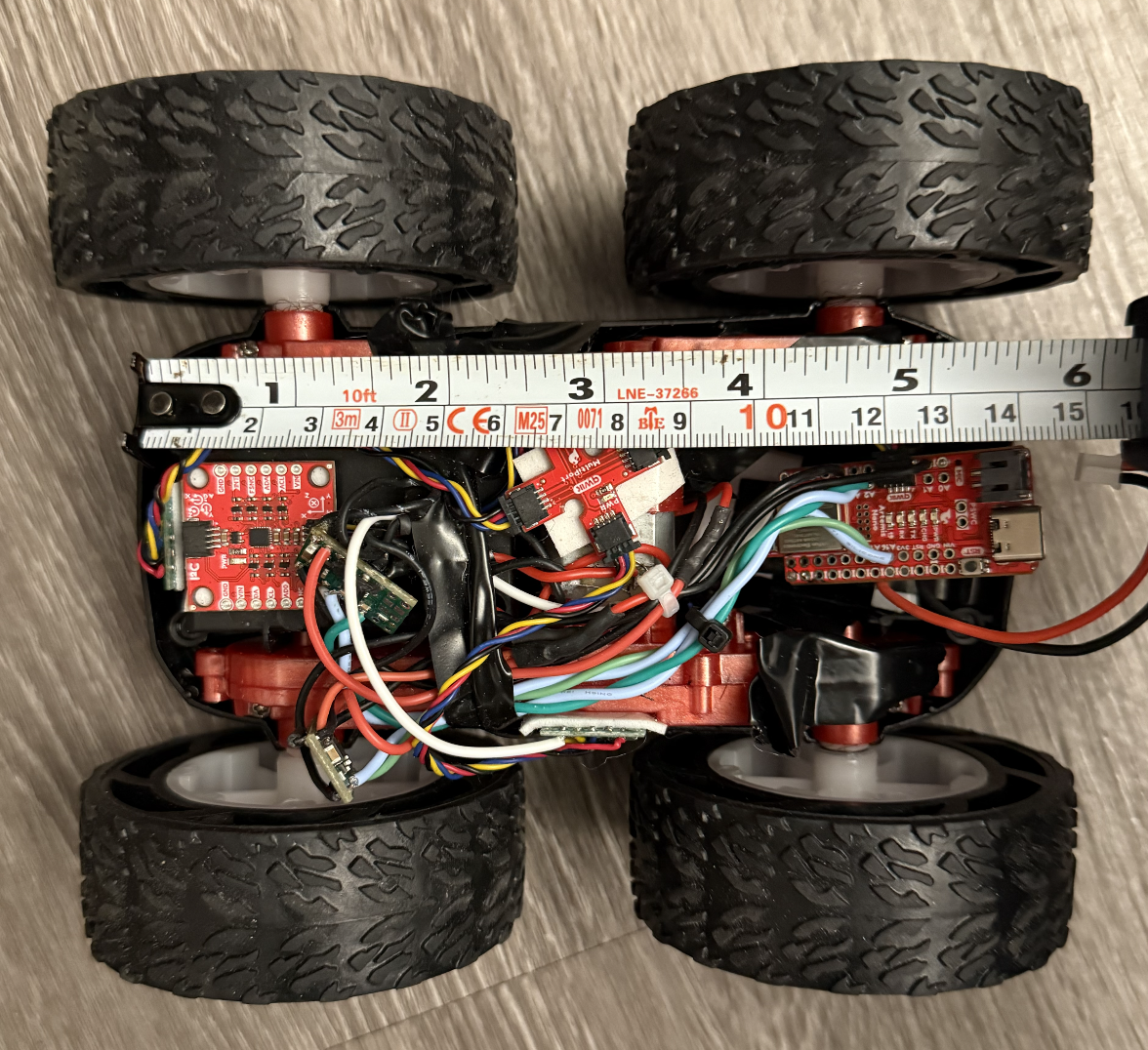
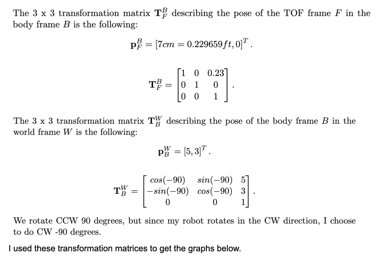
The TOF sensor is ~70mm away from the robot's center:
(3.5833333333,0.75)
(0,0)
(-3,-2)
(0,3)
(5,3)
(5,-3)
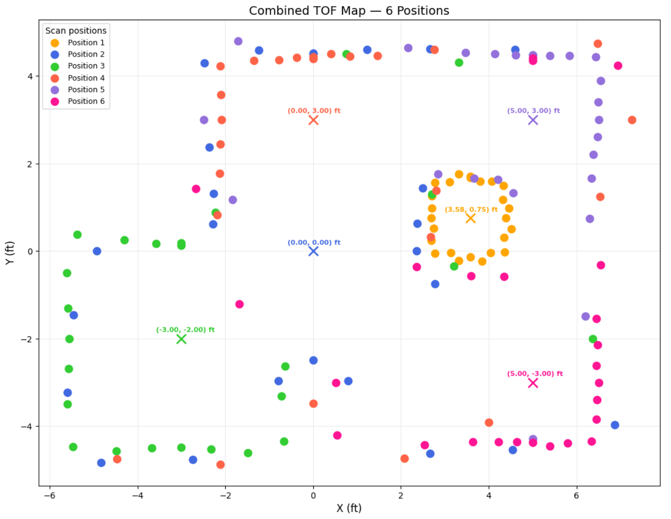
Convert to Line-Based Map:
I now estimate the walls location.
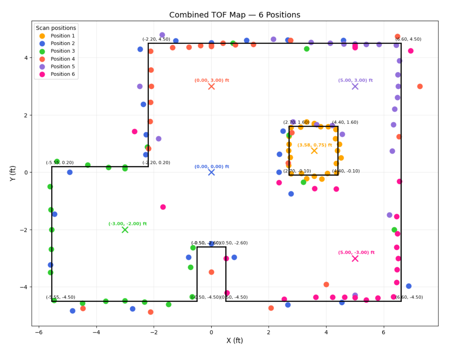
For the square at (3.58,0.75), I trusted the orange points the most because they were collected inside the square. I drew a line to divide the clusters so that each side had about the same number of points. I ignored that one pink dot to the top left of (-3,-2), which could be due to the inaccuracy of the sensor when the distance is >3m away. This dot is supposed to be a point on the topmost wall, so that is why I ignore it. If I had more time, I would take more data points around the thin wall since the points I used didn’t capture it the best.

Collaborations
Thank you, Professor Helbling. Claude helped with graphs. Hunter inspired this webpage.