Prelab
We want a fast robot, so we short the pairs of inputs and outputs as seen in my circuit diagram. This allows us to avoid overheating the chip while doubling the average current supplied to the outputs. Since the motor drivers share the same chip and clock hardware, we can do this, but not necessarily with other drivers.
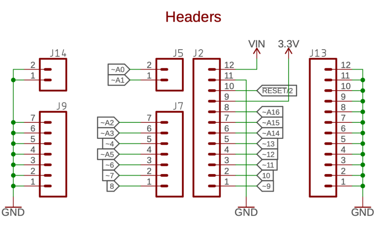
I use GPIO pins A16, A15, A3, and A2 as they are close to the BLE so that I can have the USB-C port face the back of the car and the BLE end face the motors so I don’t need as long wires. I will place the motor drivers near the front of the robot so the output wires of the driver are as short as possible connecting to the motors. As seen below, all the pins with a ‘~’ are PWM hardware pins.
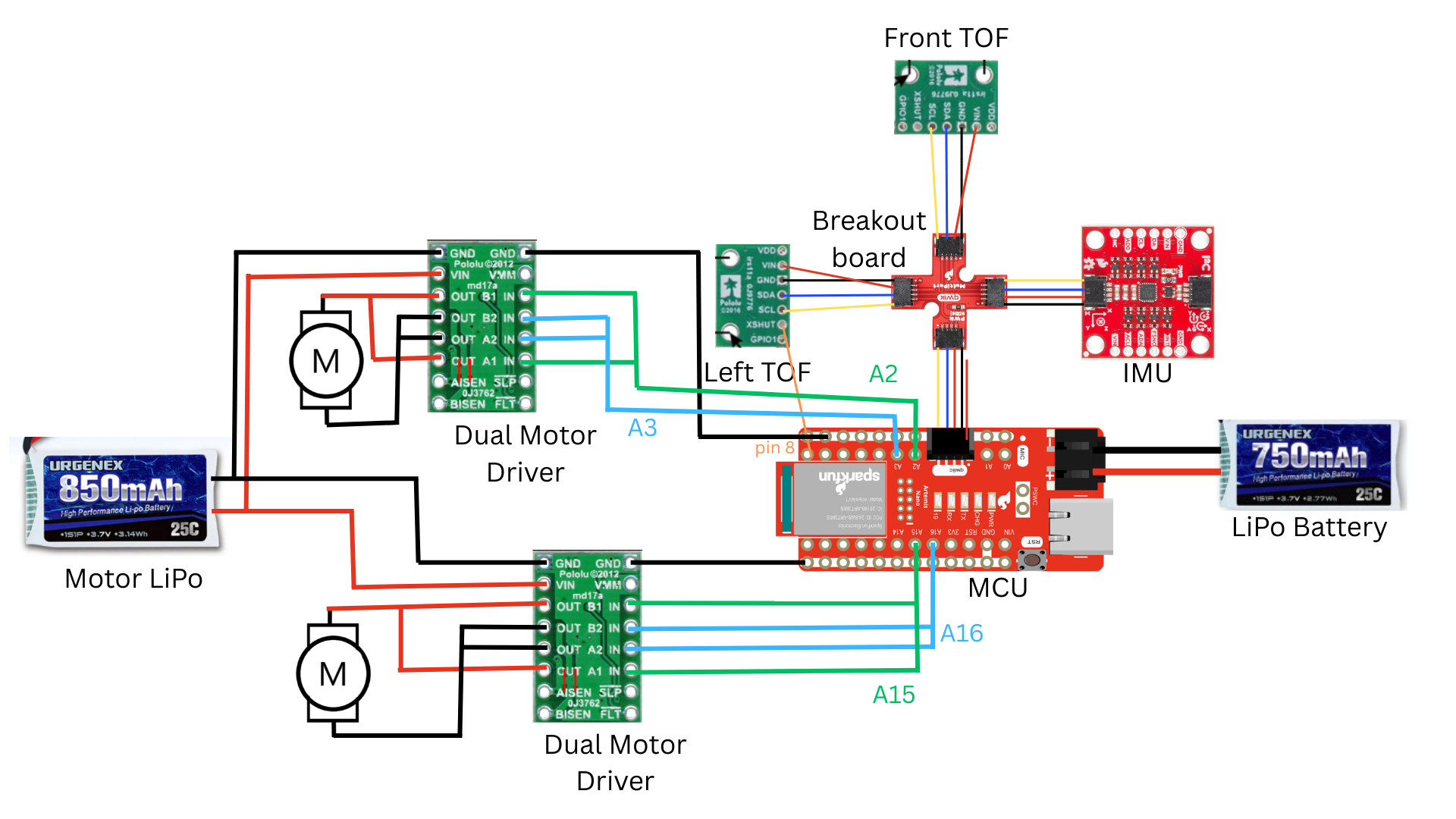
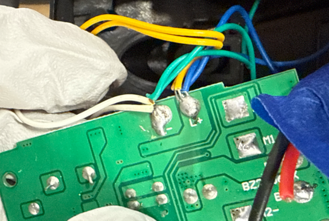
To a reasonable approximation, a DC motor can be modeled as a resistor in series with an inductor and generator. The generator creates noise that could damage the MCU if the motor drivers/motors used the same battery as the MCU. This is why we have two separate batteries with two different red power lines. They will have to share the same ground because we need a reference voltage, but there will be minimal crosstalk on the ground line. I made sure my wires weren’t too long to avoid unnecessary noise. I zip-tied and separated my power wires from the PWM input wires, and I also separated the I2C data lines. I twisted wires to prevent EMI. I color-coded red for power, black for ground, blue for A2B2IN, and green for A1B1IN.
Tasks
Test with an oscillscope
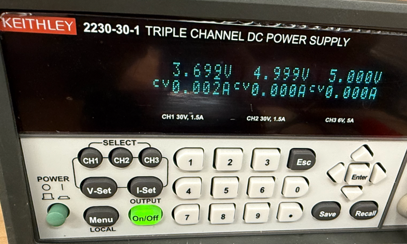
I solder all the connections for the first motor driver according to my schematic except for the outputs. Since power supplies have internal fuses and current limits, I will connect the VIN and ground of my motor driver to a DC power supply. My settings were 3.7 V (like the 850mAh battery) set to CV. Our batteries are 850mAh and 25C, so they can continuously supply 85*25=21.25A. However, I set my current limit to be 1A to be safe.
I connected the oscilloscope to common ground and CH2 to A1OUT and CH1 to B2OUT.
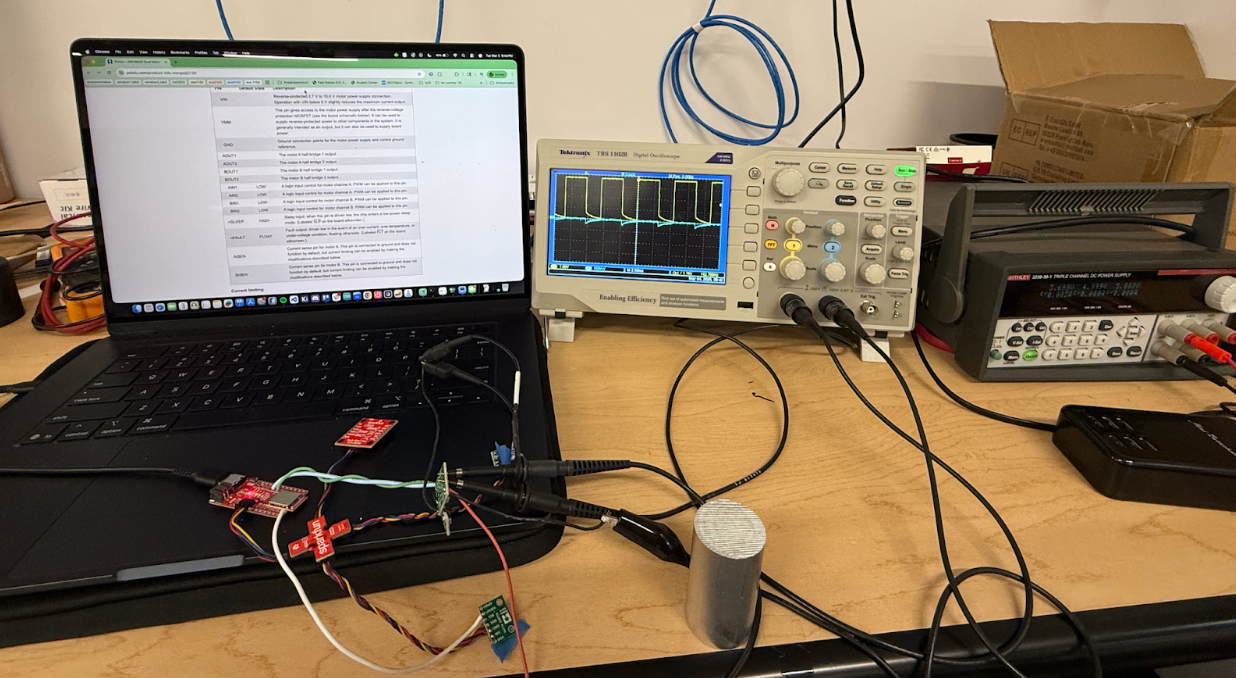
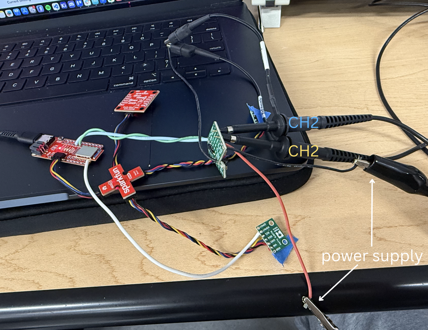
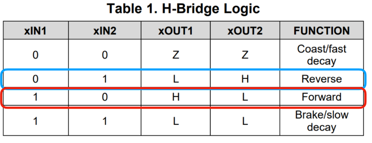
I made an Arduino script to set A15 low, which sets A1OUT and thus CH2 in blue low, and then the script takes user input from the serial monitor to set the duty cycle of A16 using analogWrite, which is outputted from B2OUT to CH1 (inspired by Aidan Mcnay).
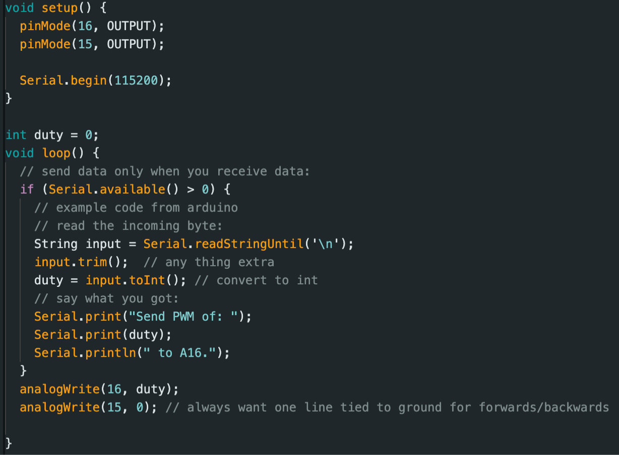
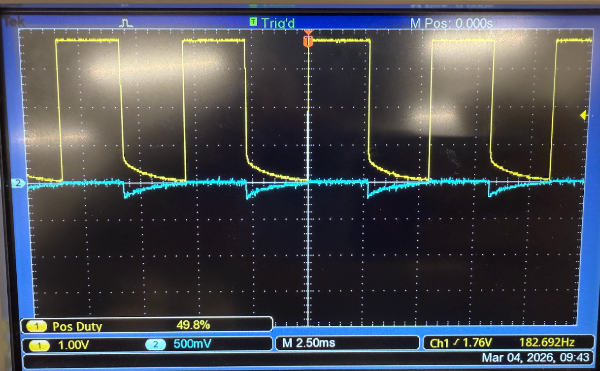
50% duty cycle, analogWrite(15, 127). Notice how the waves aren’t perfectly square due to the H-bridge's RC response.
Car Disassembly
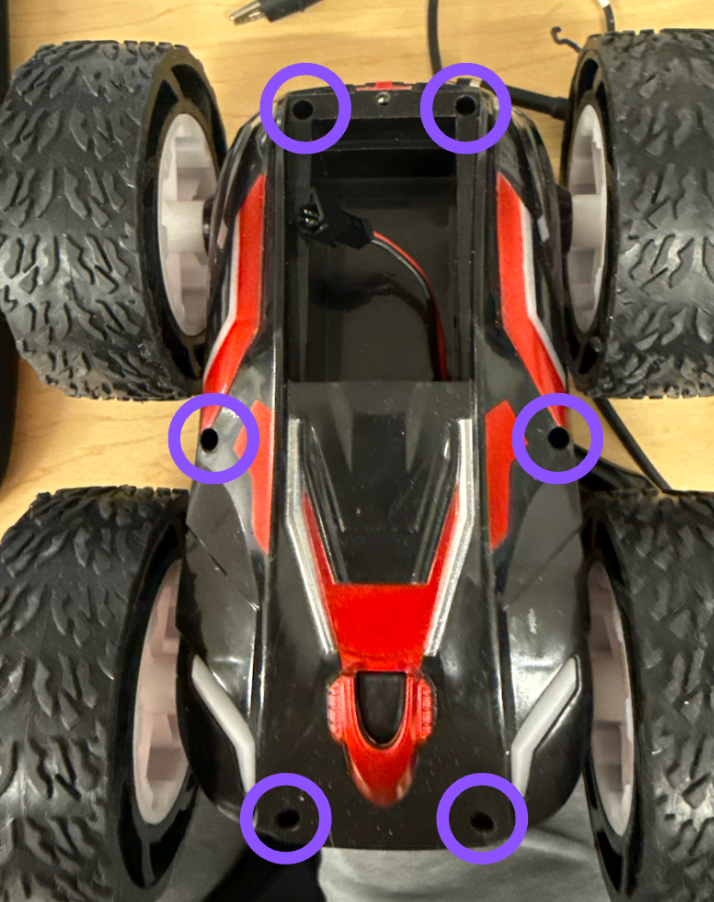
Unscrew screws circled in blue.
Cut all wires connected to control PCB.
Test one motor
I soldered one of the motors to the output of a motor driver and below is a video showing the motors spinning in both directions powered by the DC power supply.
Without the power supply:
Putting everything together
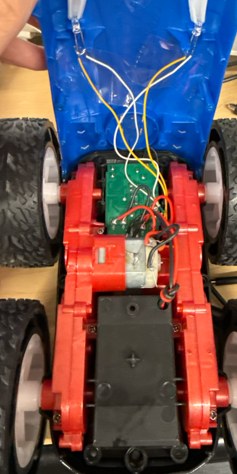
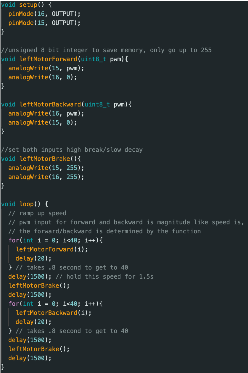
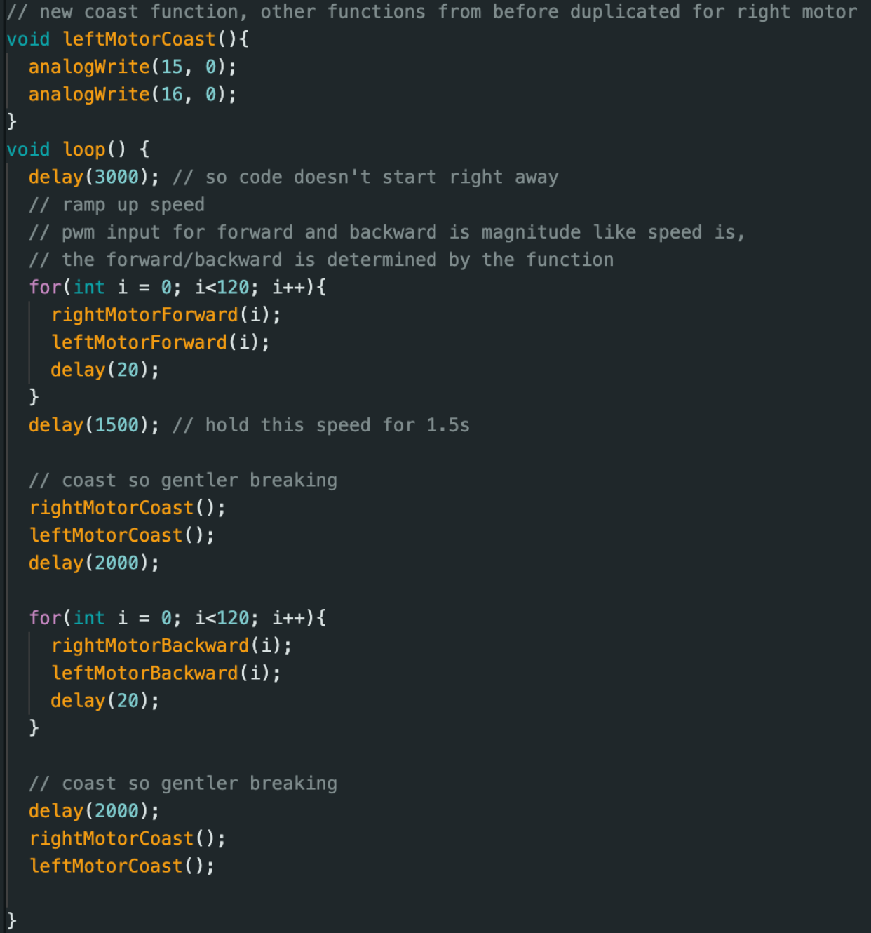
I soldered the other motor and put everything in my car. Below is my code and a video of it going forwards and backwards.
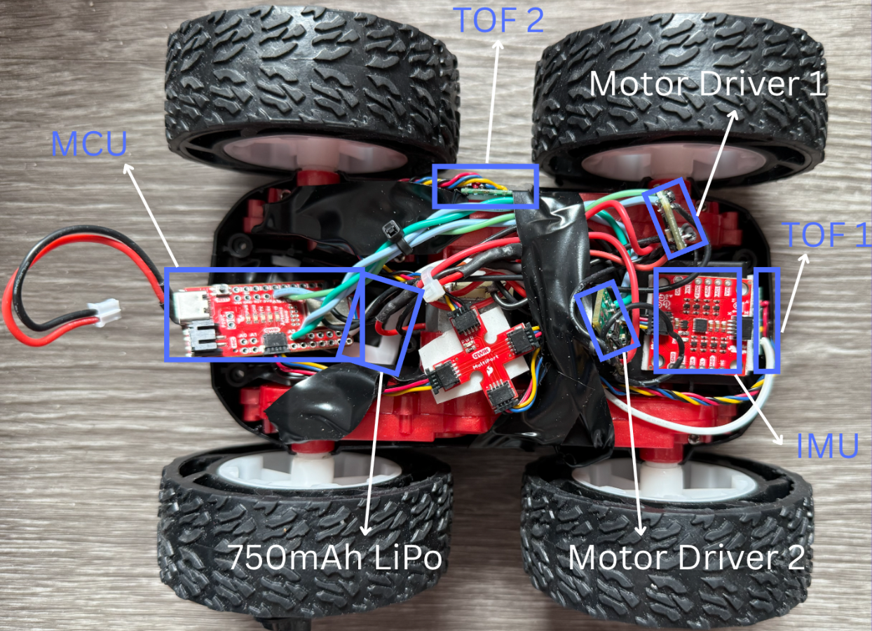
Labeled photo of my car.
Lower limit PWM
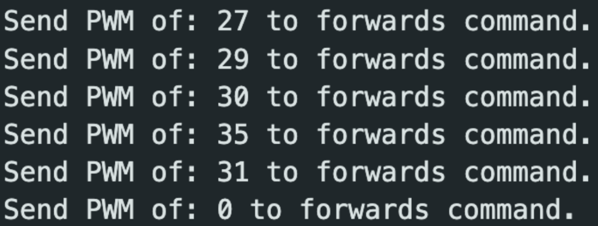
I used the serial monitor to find the lower limit PWM values. Due to the robot's weight and friction with the ground, we need a certain PWM value to get the robot moving. The tests were conducted with a full battery, but we may need higher PWM values for lower battery. I need a minimum PWM value of 35 to get it moving from rest and a minimum of 20 to keep going forwards. For on-axis turns, the minimum was 140 from rest and 130 to continue. Different surfaces will also make it easier/harder to overcome the friction with the ground, and thus different lower limit PWM values exist for different surfaces.
Calibration to drive straight
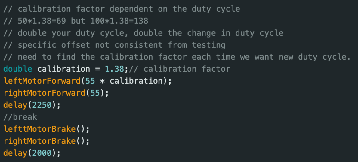
With no calibration, the robot drifts to the left. The right motor spins more than the left. Thus, we need a calibration scalar >1 to scale the left motor’s duty cycle. I would guess a calibration factor and based on whether it went too far left or right, I would move the calibration factor up or down, respectively. Eventually I got a calibration factor of 1.38. As seen in the video below, the front of the car starts at 112 inches from the wall and ends at around 30 inches, which is a distance traveled of 6 feet and 10 inches.
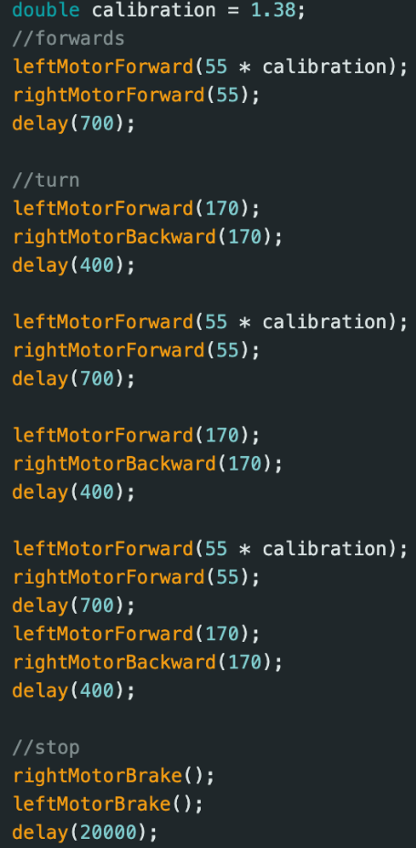
Open loop control drive in a triangle
Collaborations
Thank you Prof. Helbling for help in lab. I referenced Aidan McNay's, Aidan Derocher's, Stephan Wagner's webpages. This website template was inspired by Hunter.