Prelab
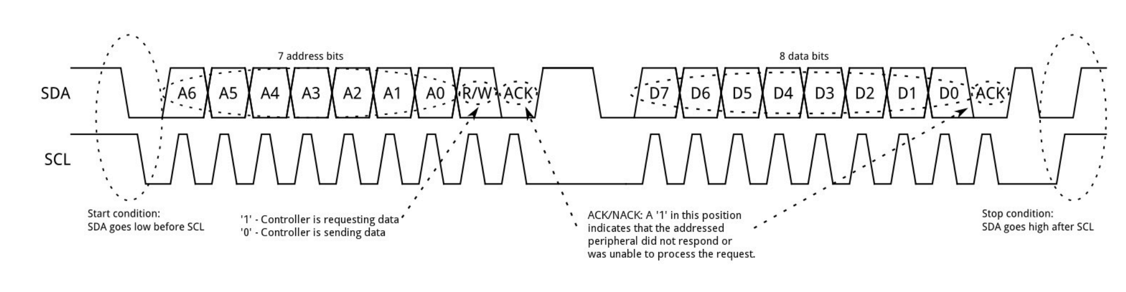
Looking at the datasheet for the VL53L1X, our TOF (time-of-flight) sensor’s I2C 8-bit address is 0x52 or 0x53 depending on if the controller is sending data or requesting data, respectively, as seen below. If we shift this address right by 1 bit, we get 0x29—the 7-bit I2C address of this sensor.
In this lab we will be focusing on the VL53L1X time-of-flight (TOF) sensor to detect the distance of obstacles in front of the sensor. It detects distance by measuring how much time it takes for the infrared light to bounce off an object and back to the sensor. We will use it in future labs for object avoidance or to determine how close an object, like a wall, is.
We have two TOF sensors, but they both come with identical addresses from the factory. Since they share the same I2C address, we cannot address both simultaneously on the same I2C bus without doing one of two things. One method is to use the hardware shutdown pins on the sensor and enable one sensor while disabling the other and then toggle between them really fast to get data from both. As an example, you turn on TOF 1 and read TOF 1 while TOF 2 is off. Then you turn off TOF 1 and then turn on TOF 2 and then read TOF 2 and then rinse and repeat. You can think about it like context switching, where you switch between the two sensors so fast that it seems like you're getting the data simultaneously when really you aren't. The other method is to use software to turn off one TOF sensor and then alter the address of the other TOF sensor that is on.
Both options have their pros and cons. For the toggle shutdown method, you will have a simpler initialization process and won't need to change the I2C addresses. However, the con of this method is you will sample data from both of the sensors at a slower rate than if you had them both sampling at the same time. For the software method of changing the addresses, a pro is there is less wiring since you only need to control the XSHUT pin of one TOF sensor, and then you will also have a faster sampling rate because you can poll each sensor simultaneously. The con is that it might be slightly more complex to set up in software and may consume more power (but probably a negligible amount compared to the amount of current our motors draw).
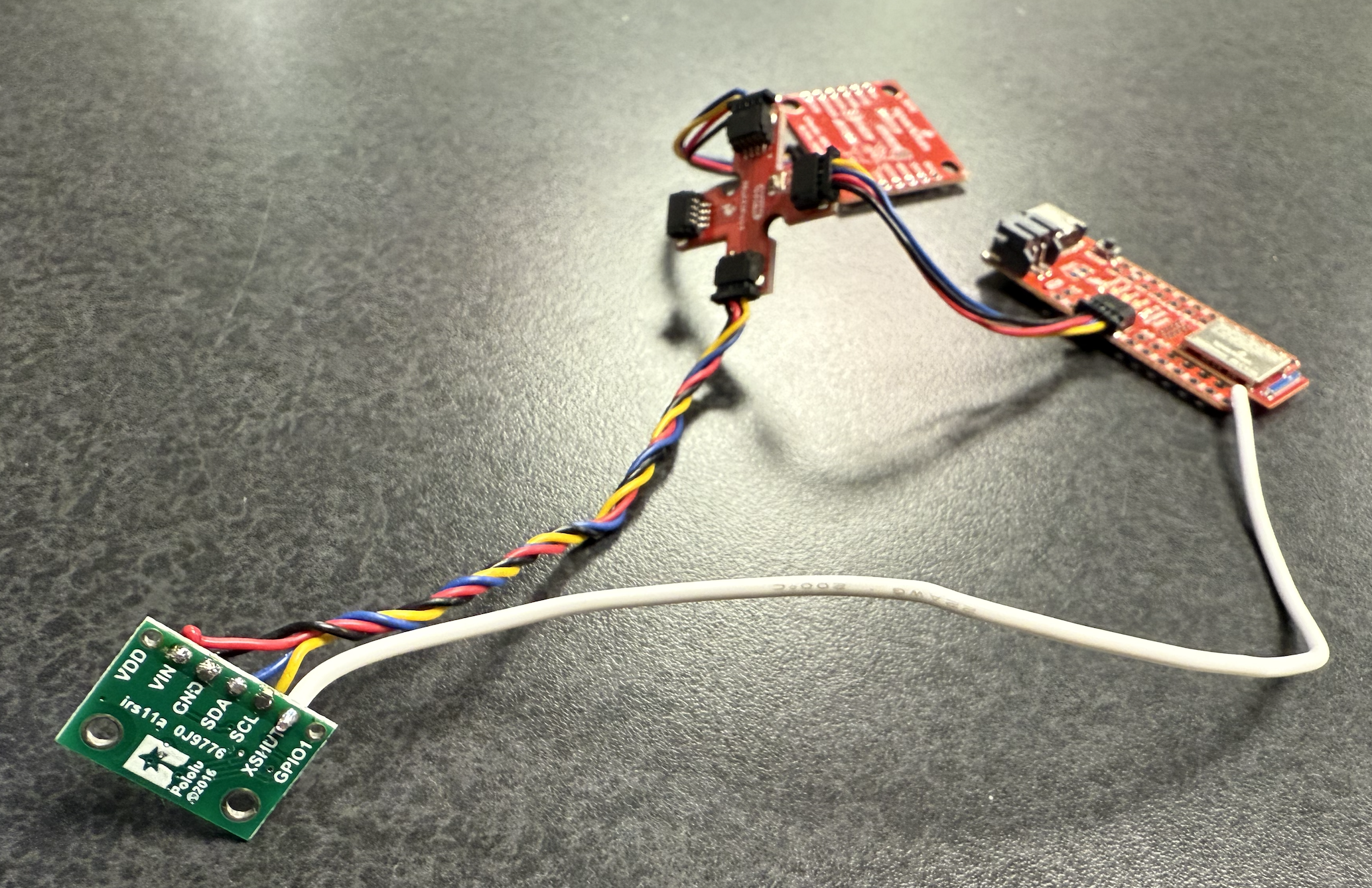
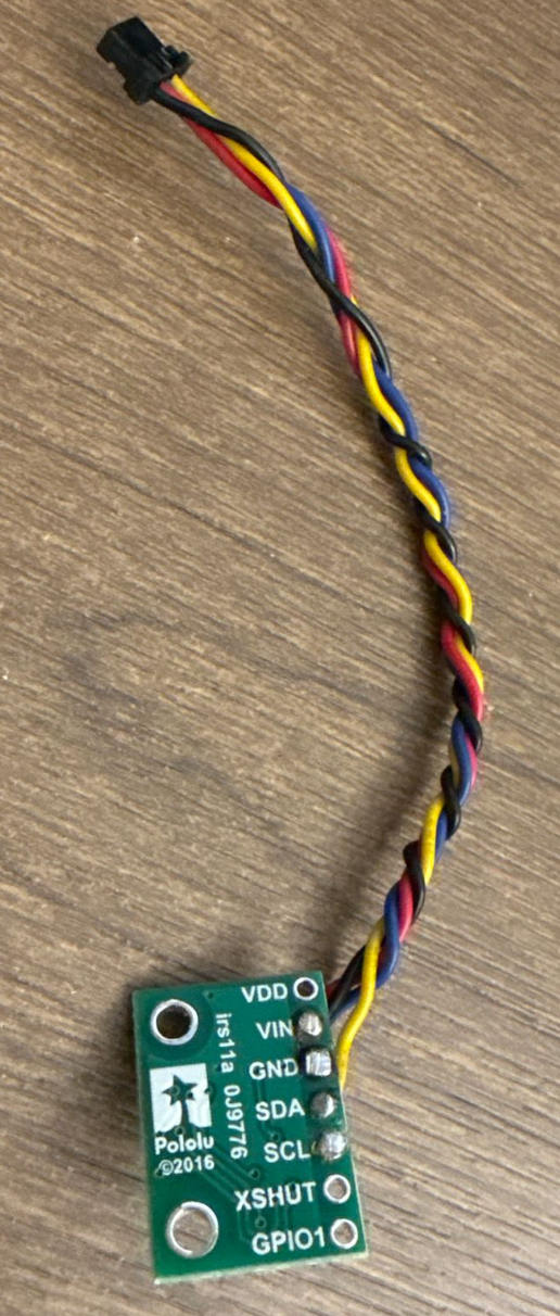
I opt to take the software approach to alter the address of one of the TOF sensors when it is powered. I chose this option because with how fast the robot is moving, it is most optimal to be polling both sensors simultaneously; it involves less wiring (I only need to wire one XSHUT pin instead of both); and the power consumption difference is negligible. I need to solder at least one of the TOF sensor’s XSHUT pins to a pin on my MCU because if both devices are on and I try to change the address of one of them, they will both receive the same message because they are on the same I2C bus, and then both addresses will change. So I will need to hardware shutdown one of the TOF sensors, change the address of the TOF sensor that is still on, and then turn on the TOF sensor I originally turned off. Then, they will have different addresses. I chose 0x36 as the new address for the sensor I am keeping on because it is my favorite hex number and does not conflict with the 0x29 address of the original TOF sensor or the 0x69 address of the IMU. Below is a picture of the TOF sensor’s XSHUT pin soldered to the MCU’s digital pin 8 with the white threaded wire.
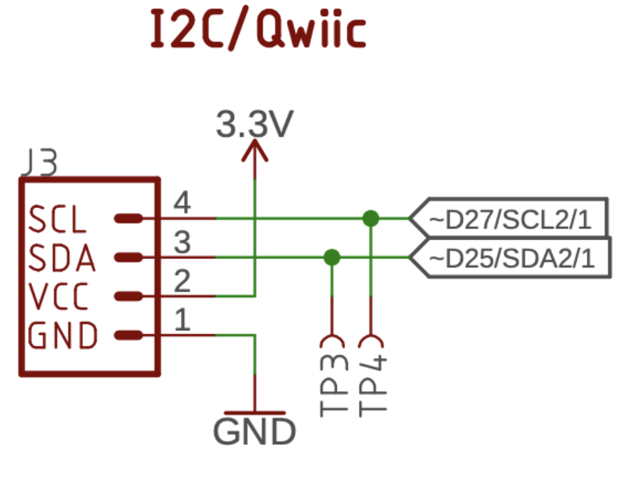
The Qwiic connector is connected to digital pins 27 and 25, seen below, which are SCL2 and SDA2, respectively. Digital pin 8 is SCL1 and doesn’t seem to be used anywhere else in the schematic. We will be only using one I2C bus, and there are plenty of digital pins to spare, so I chose this one for the TOF’s XSHUT pin. I was also considering using pin 9, but that pin is on the other side of the board, so I just chose pin 8 since it is on the same side of the board as the QWIIC connector.
Since I have two sensors, I will have to think about where to put them on my robot to get the most benefit out of them. Of course, I will put one sensor at the front of the robot to detect obstacles right in front of me that I might collide with. With the case removed, the front bumper area has a flat surface, which is important because I do not want the sensor to tilt even slightly towards the ground; otherwise, it will measure the distance to the ground instead of detecting obstacles in front of it. I opt to put the other sensor on the left side of the robot so that if I am going down a hallway, I can see if there is a wall next to me, or if I am in a maze, then I won’t have to turn as much to see all around me since I can see in front of me and to the left of me simultaneously. I was thinking about putting it at the back of the robot but thought there would be more scenarios of obstacles next to the robot instead of behind it. Mainly my robot will not see to the right or behind it without rotating the robot. So if it takes a right turn, not in place but an arcing turn, it might hit an obstacle if there is an obstacle directly to the right of it since it may not see this obstacle in time if the robot is going fast enough. Also, if the robot ever gets flipped over, the back of the robot will be facing forward, so we will no longer be able to detect obstacles in front of us in this new orientation.
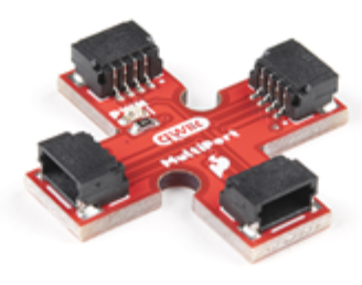
I was confident in all my soldering, so I made those connections permanent. The Qwiic connections are the only ones that are detachable so that if I want to move the TOF sensor to the left instead of the right side or back instead of the front side, I can with the 4-way Qwiic connector shown below:
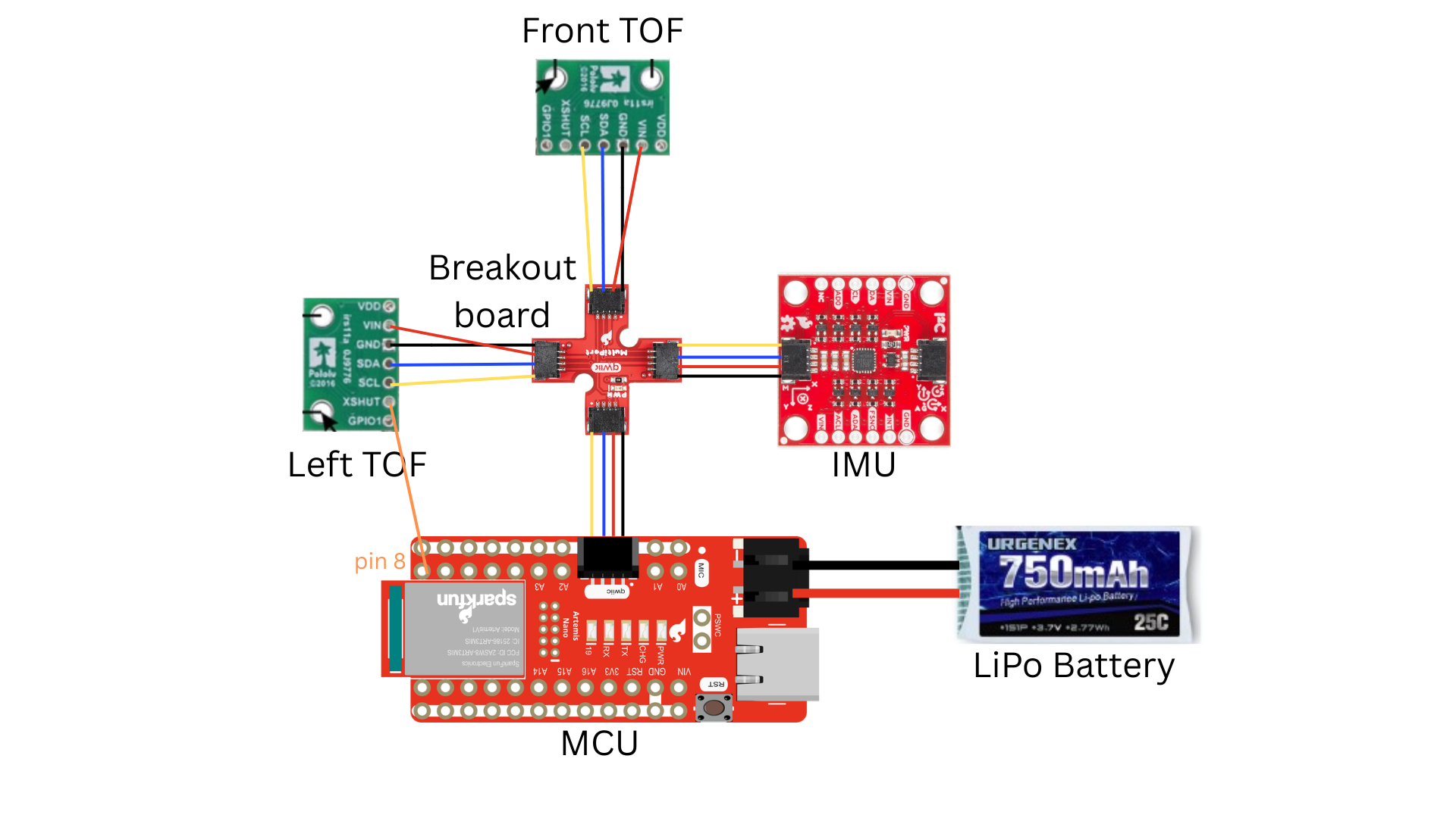
I decided to mount the wires so that the soldered part is where the pin names are and the wires come out on the side with the sensor, as shown in the image below. I did this so that the TOF sensor can sit flush against the surfaces I attach it to. The image above shows where I will place the sensors, and I measured how long the wires should be by putting the sensors where I want on the robot and the MCU in the middle and then stretching the wires out from there by eye. I will use the long Qwiic connectors for both TOF sensors to reach the front and left of the robot. The circuit diagram is also shown below.
Lab Tasks
Battery Setup
I carefully cut the wires of my battery one at a time. If I cut it at the same time, I will short power to ground, and the battery will puff up. I soldered the black end of the battery to the red end of the JST connector and heatshrinked the exposed wire. I soldered the red end of the battery to the black end of the JST connector and heat-shrinked the exposed wire. The polarity on the JST connector was flipped; I want to ensure the red of my battery goes to the positive terminal of my MCU and the black of my battery goes to the negative terminal of my MCU. I upload some simple code to my MCU and power up the MCU by only using the LiPo and not the USB-C cable, and I send some simple BLE messages from Lab 1 between the MCU and my laptop to make sure the MCU can work without the USB cable. I won’t be connecting the USB-C cable when I put the MCU in the car in lab 4. You can see the echo command working in the video below. The video only shows the echo command—I already connected to the Bluetooth beforehand since it takes a few seconds. Note that in the video the MCU is only connected to the LiPo battery and via USB-C.
Setup of the first TOF sensor
I then installed the SparkFun VL53L1X 4m laser distance sensor library and connected the Qwiic breakout board to the MCU and then connected a TOF sensor and the IMU to the breakout board as seen below.
You can also see the white wire that connects the XSHUT pin of the TOF sensor to pin 8 of the MCU. As mentioned before, I used the long Qwiic cable for both TOF sensors since they will be the farthest sensors from the MCU. SDA is blue, and SCL is yellow. I made sure to take off the protective film. I run the Apollo 3 Example-5_wire_I2C demo code and get the following output:
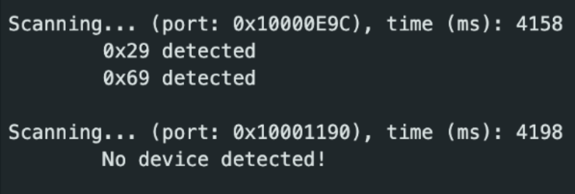
We care about the first port listed since that is the Qwiic connector I2C bus. 0x69 is the IMU I2C address, and 0x29 is the TOF I2C address. This address matches what we expect for the 7-bit address of the TOF sensor as discussed in the prelab at the top of this report. I skimmed the code to understand in general how the I²C commands work to transmit data and verify data was received.
Choosing range mode
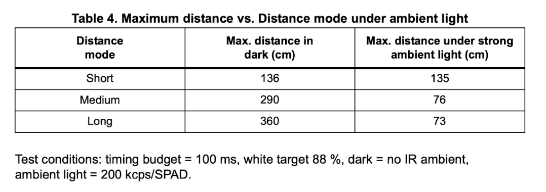
There are tradeoffs between the short, medium, and long modes of the TOF sensor as seen in the table above. The default mode is long. Starting with the short mode, some pros are that it is accurate at close range and because it is limited to 1.3 m, there is the lowest chance out of the three modes to have interference or crosstalk between two sensors. However, crosstalk shouldn’t be much of an issue since the sensors are pointing in perpendicular directions away from each other. The short mode also has the best ambient immunity, so we will still get good data despite slight changes in the environment. The only con for this sensor is that it can’t see as far as the other modes.
The medium sensor is a compromise between the short and long modes and thus has a mix of their pros and cons. It will still have decent range but lose some of that ambient immunity. Thus, it will experience more noise and sample a bit slower but also sample up to slightly farther distances.
For long range, the pros are that it can read much farther distances, up to 4 m, which is better for more open spaces with fewer obstacles. The drawbacks are that it will be more sensitive to ambient noise, there will be more chance of crosstalk, and it will sample slower.
In general by lengthening the time between readings, you are able to read further distances. However, this will slow down your loop speed, and the longer you wait for the signal, the more cycle times you are wasting that you can be doing something else with, like control loop logic. You want the sensor measurements to keep up or be faster than the model of your car (how fast the car can go), so it is a trade-off between accuracy and distance and speed of data collection. I choose the short distance mode because it is the best for indoor robots and obstacle avoidance. Also, since my robot goes so fast, I want to sample data as quickly as possible, and this mode also allows me to do that. If the distance is too short for me to recognize and react to obstacles, I may look into the medium sensor in future labs. For example, for labs 11 and 12, we will be slowing down our robots, so it may make sense to slow down the timing budget to around 140 ms to have improved reliability errors, and since the car is moving so slowly, the sensor will still be going fast enough. But, for fast stunts, we do not need such long-distance measurements or slow timing budgets.
Testing accuracy and sensor data
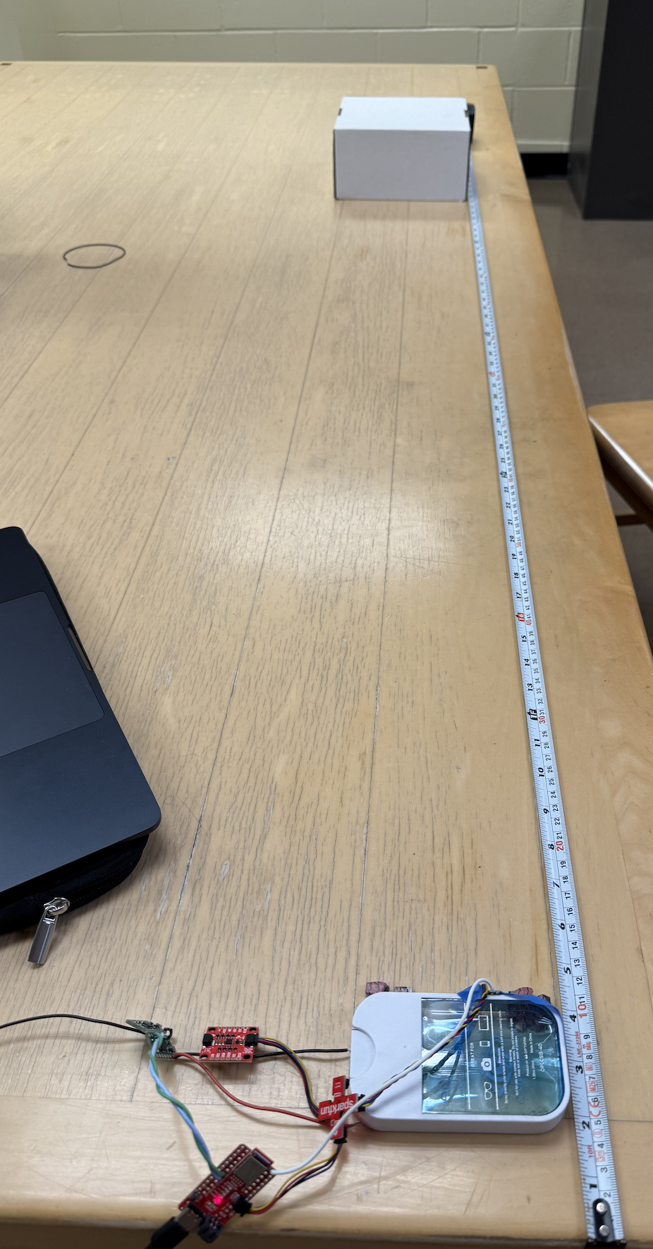
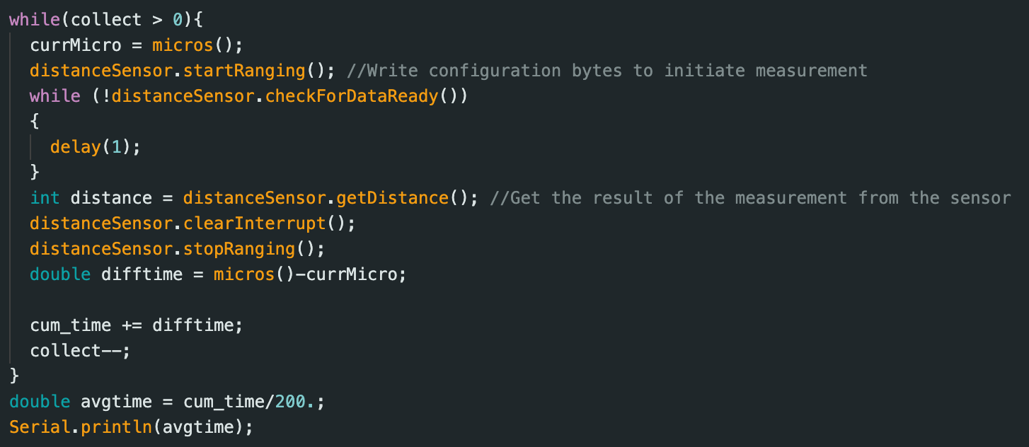
Since I chose the short distance mode, I made sure to put in the command “distanceSensor.setDistanceModeShort();” in the setup in my Arduino script since the default distance mode is long. Then in my “void loop()” I wrote a simple program that collects the cumulative distance over 200 measurements, and then I divide this cumulative distance by 200 (the number of measurements) to get the average distance over 200 data points. The whole time, I kept the white box in infront of the sensor at a fixed distance since the test conditions in the table above were 88% white. I repeated this trial multiple times for multiple fixed distances to collect the average reading from the sensor and compare it against the actual reading with the ruler.
At first my data was inaccurate anywhere higher than 60 cm, but it turns out my sensor was reading the ground instead of the box in front of it. I redid the tests with the sensor angled up slightly more by putting puzzle pieces under the object I used to tape my TOF sensor too.
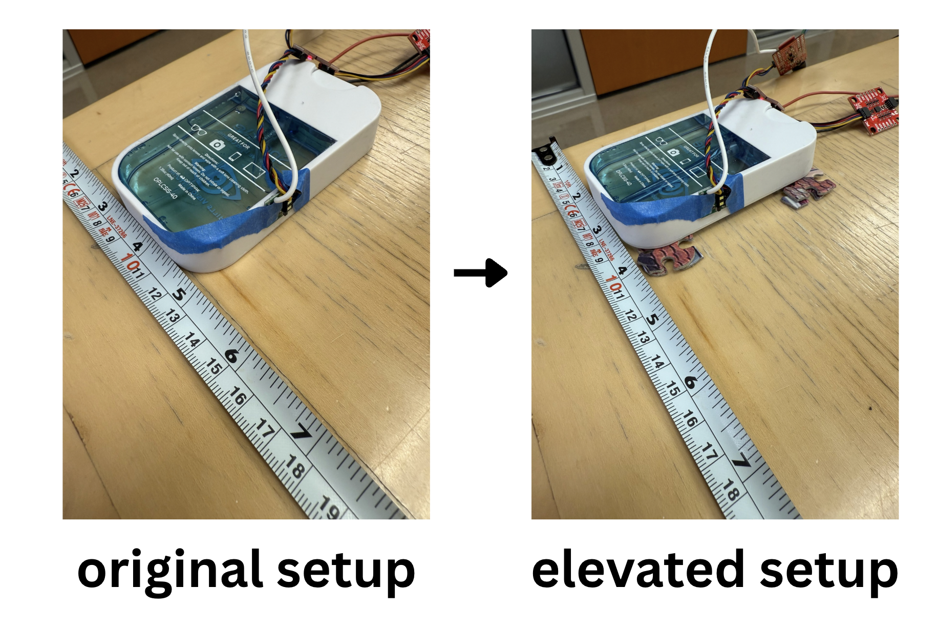
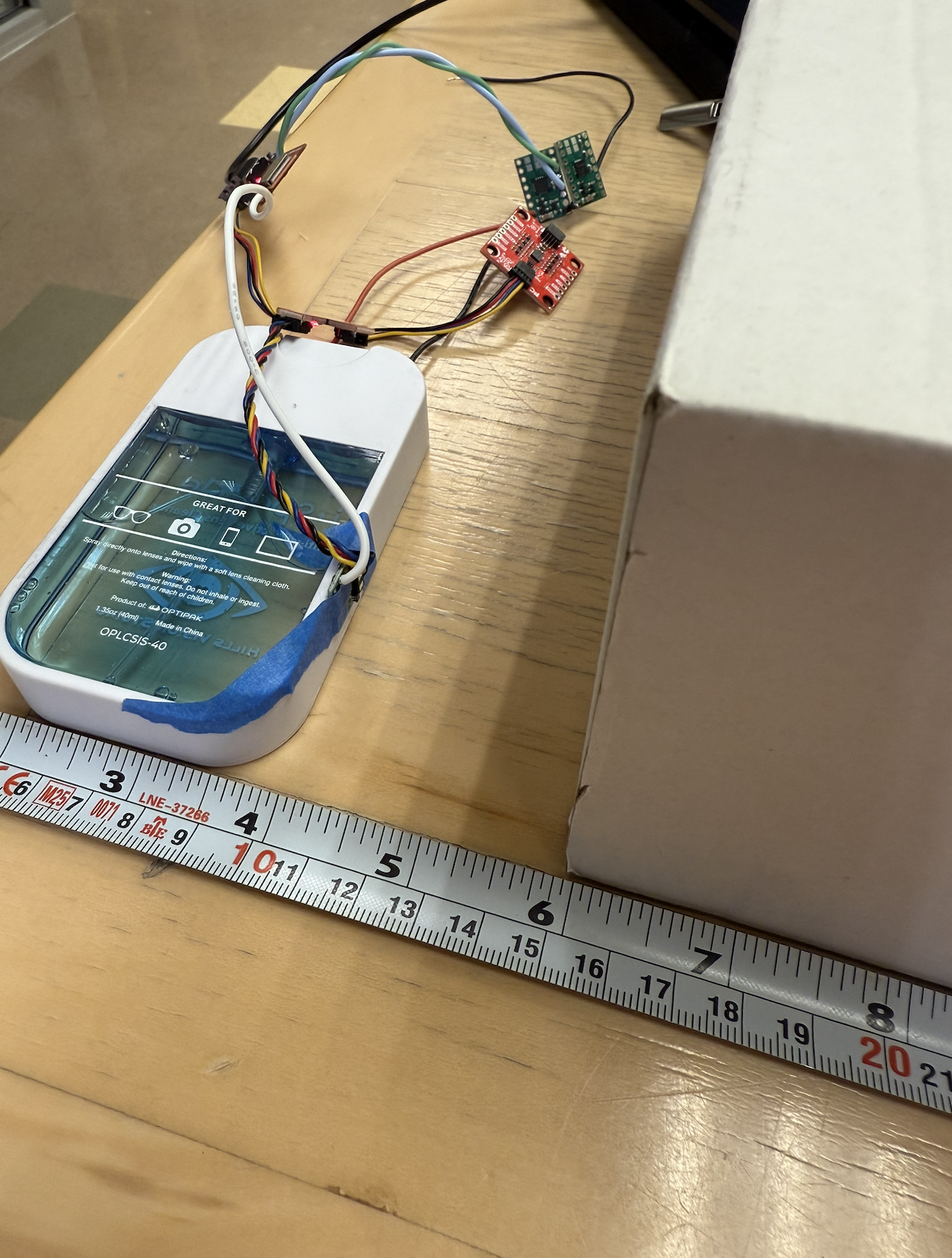
The rest of my setup is shown below, where you can see the tape measure and white box and the TOF sensor. The sensor is at the 10 cm marking of the ruler, and so I made sure when I wanted to measure the actual distance of 5 cm, I would put the front of the white box at the 15 cm mark.
I also have the graphed data of the measured actual distance from the measuring tape vs. TOF data from Excel shown below.
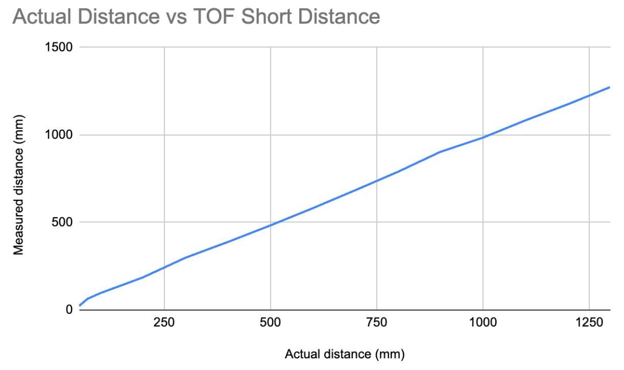
The graph is mostly linear with a slope of 0.993, which is almost 1. So the answer is fairly accurate from 0.05 to 1.3 m.
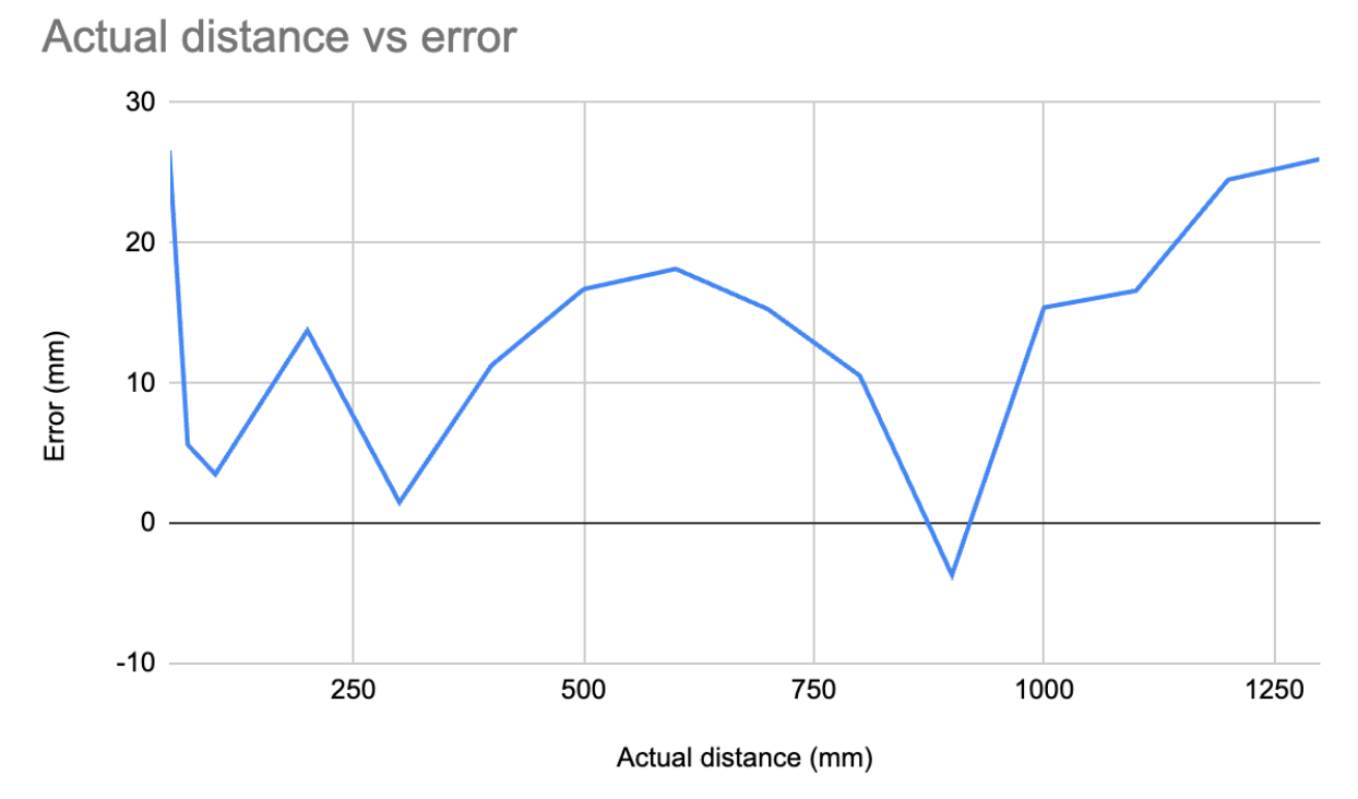
Here is a graph of the error vs. the actual distance the sensor is. The error is just equal to (actual - measurement). The error isn’t very constant, and the average error is around 13.44 mm, which is around 1 cm, so that is not worth me making any special offset. Being off a couple of centimeters does not matter for the stunt lab. If I need more exact data, I will tune the distance sensor for the new environment where it needs more precise measuring. I do not think it is worth calibrating the sensor before putting it on my robot.
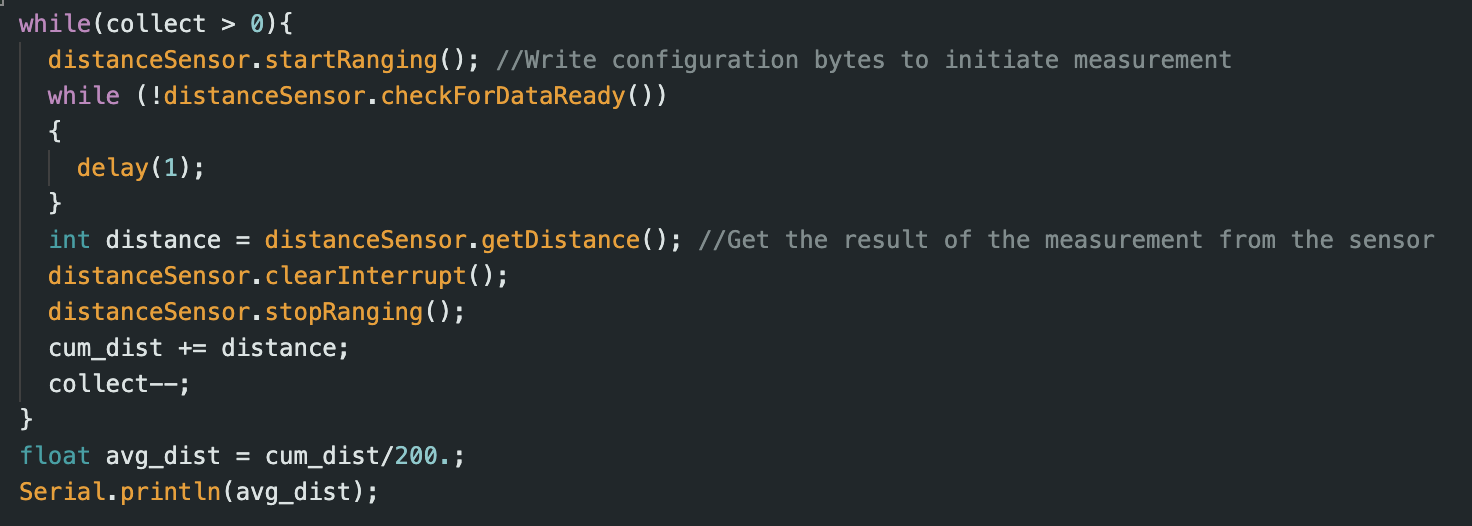
Below is the code snippet of the script I used to collect 200 data points and then average them
I also won’t delve too deep into this, but below is a graph of sending distance data over BLE just as proof of concept. This was in the long-distance data mode and I just moved my hand towards and away from the sensor for a set time period.
To summarize, the ToF sensor range is from 0.05 m to 1.3 m but is the most inaccurate (by around 2.5 cm) for very close distances like 5 cm and very far distances like 1.3 m. So basically in the middle of its short-distance range, it was fairly accurate but fell off in terms of accuracy at the extremes of the range. I measured the accuracy by the slope of the measured vs. actual distance to be 0.993, and if it were fully accurate, the slope would be 1. I also looked at the error as discussed earlier, and an average error of 1.3 cm is fairly accurate. I thought the error would be repeatable, but from my error graph, the error wasn’t really repeatable because if it were, it would be a straight line with zero slope for the error vs. actual distance graph (constant error). Instead, it kind of jumped all over the place. I measured the ranging time for multiple different distances and averaged the time over 200 trials for each distance and always got around 50.5 ms. For example, at 10 cm I got 50588.56 µs. This should be fast enough for our purposes, but later, if I need a faster ranging time, there is a command to change it. However, that will sacrifice my accuracy.
2 ToF Sensors and the IMU
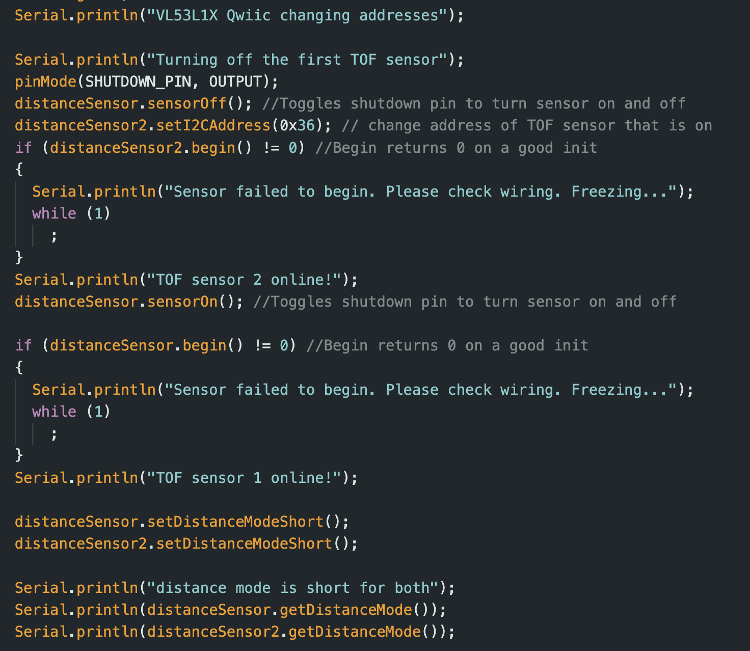
As discussed in the prelab, I will have to use the XSHUT pin to turn off one of the TOF sensors and then reprogram the address of the other sensor that is on. In the video below, I poll the distance measurements from both sensors and move both of my fingers up and down to see that both data are read at the "same time". This means I have successfully set up the TOF sensors to work in parallel. They seem to have different errors, but this is something I can tune in future labs. I had it in the video so the sensor on the left corresponds to the distance measurements on the left of the serial monitor, and the sensor on the right corresponds to distance measurements on the right of the serial monitor. I also display my setup code for both sensors below. I do not show my data collection code since it is the same as the previous part, but now I am just collecting data from two sensors instead of one. I print the collected data at the end of the loop to avoid slowing down the polling.
TOF Sensor speed
We don’t want our code hanging unnecessarily while we wait for the measurement to finish. We no longer delay to wait for the measurement to be ready, but we do print the time that each loop iteration takes. When we don’t collect the data and are just printing the loop iteration time, the time averages around (6525+7239+6285+7236+9303+7268+8243)=52099/7=7.4 ms. But when we do collect distance data, we wind up spending (9736+14862+9758)/3=36311/3=11.5 ms on average, which is almost double the time. Some of this delay is probably due in part to the print statements and the start and stop ranging, which takes time to turn on and off the sensor again and again. However, there is a common trend that collecting measurement data takes longer than just the raw loop, which makes sense. Thus, the timing budget/time it takes for us to measure data is what is slowing us down instead of the loop speed/clock speed, which makes sense. The limiting factor is collecting the distance data since before we measure the data, we must wait until the data is ready. Playing with the sensor's timing budget and removing the print statements could improve the rate we collect distance data.
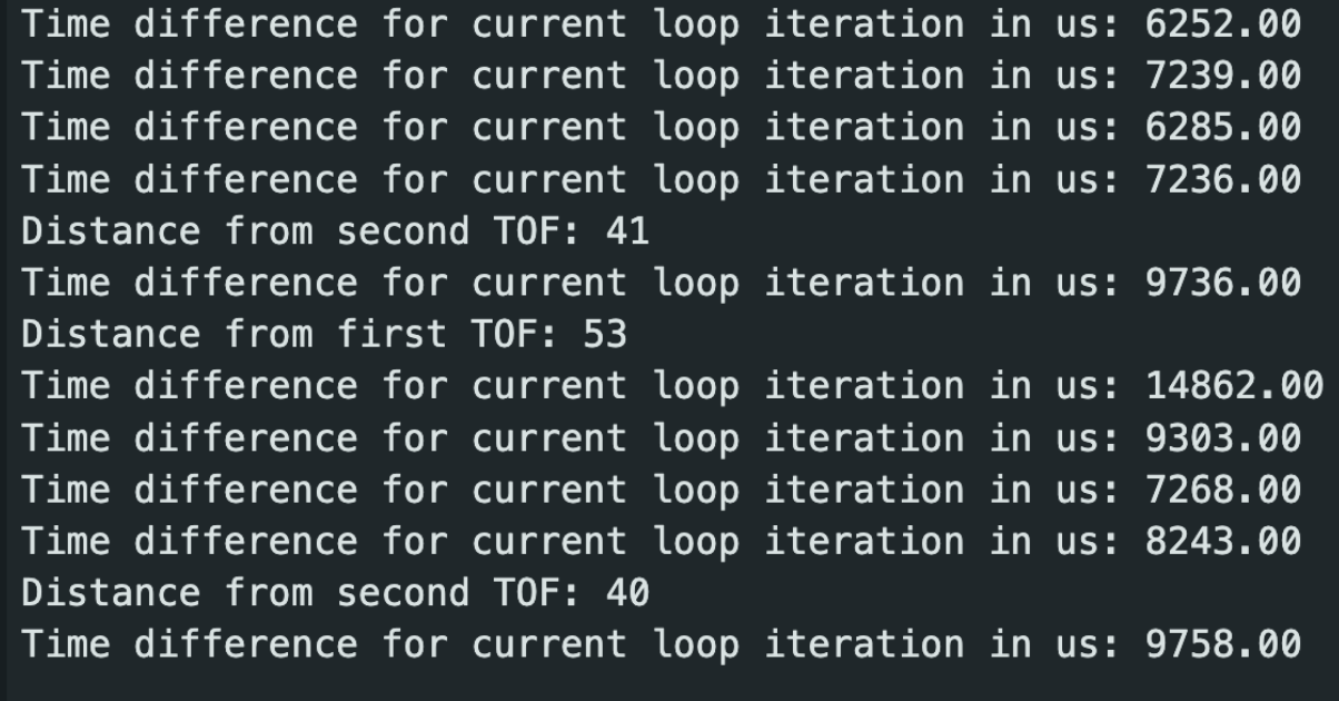
Below is the code I wrote to test this loop and sensor speed. Note that I stop ranging after clearing the interrupt but make sure to start it again after printing the distance data so that it is ready for the next time we try to collect data.
Lastly, I edit my lab 1 and 2 code so that I can record the data for the two TOF sensors and the IMU for x amount of time and send it via BLE to my computer to be plotted.
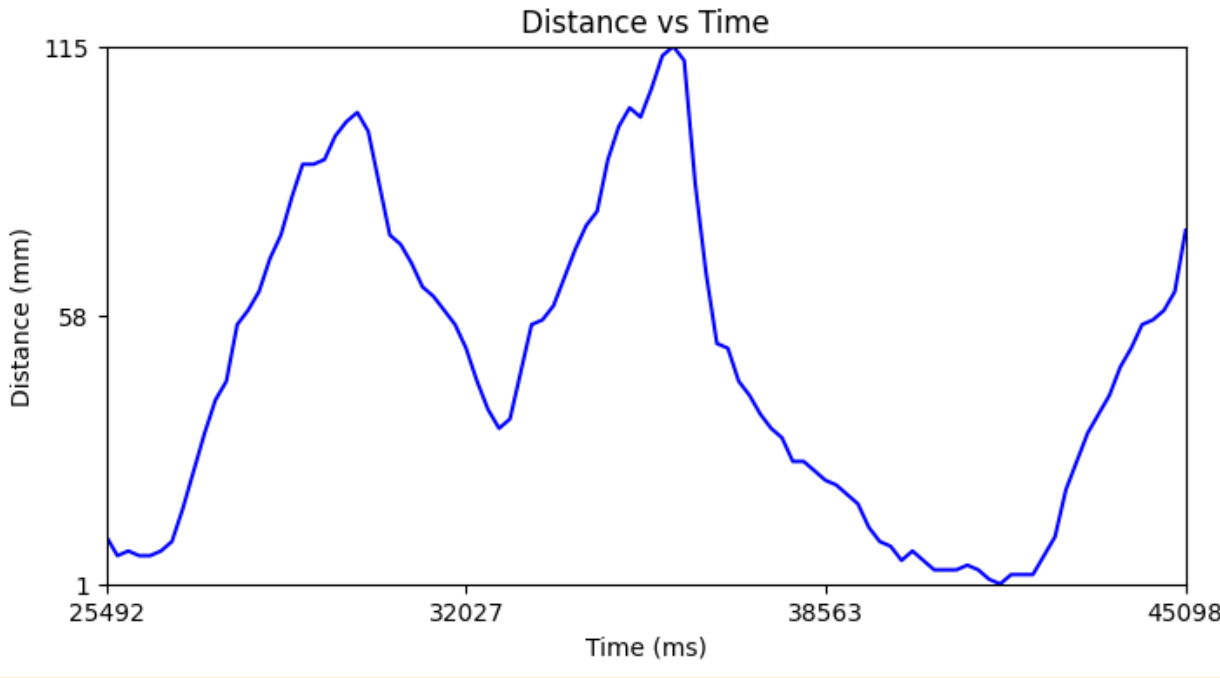
Distance v Time for both TOF
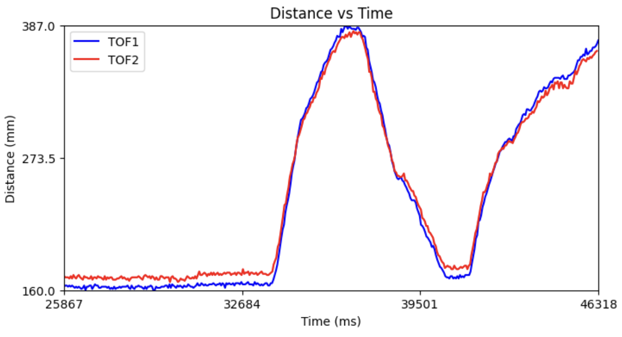
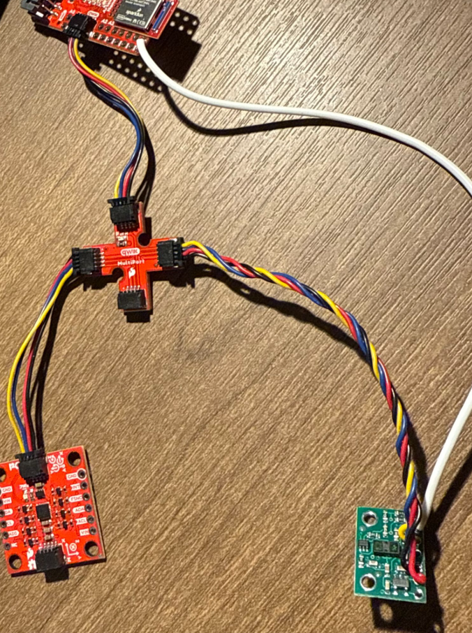
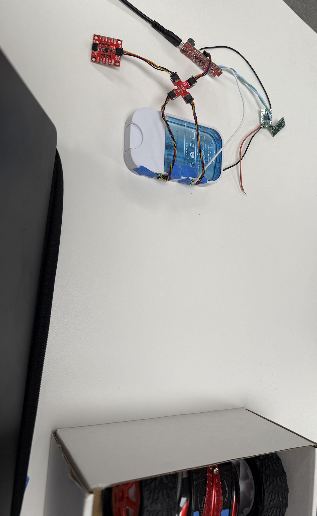
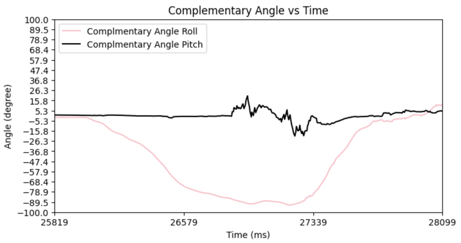
Above is the graph of data sent over BLE for both TOF sensors. Note that I also collected IMU data during this time concurrently but did not plot it on the same graph to avoid clutter. The y axis would also be different. Below is my graph for angle vs. time. Since the IMU data collects faster than the TOF data, I first tilt the IMU sensor about its x-axis so you can see the complementary filter of the roll changing. After I move the IMU sensor, I begin to move the box in front of the two TOF sensors back and forth. See how in the graph above, from 25867 ms since the program started to around 33000 ms since the program started, the distance measurements from both TOF sensors are constant. This is because I did not move the box while I was moving the IMU around, but after I was done moving the IMU (since it collects data faster), I then moved the box back and forth. The two TOF sensors are next to each other, so they should read the same value but read slightly different values, which I can correct in later labs. They seem to measure around the same distances in mid-range distances like 200-350 mm but start to deviate at higher distances of around 360 mm and more and smaller distances of around 180 mm and less. This could also be because as I was moving the box back and forth, I could have slightly tilted the box, so these measurements could be accurate. Once again, we notice that the TOF data collection is the limiting factor of our robot or what is slowing us down. We collect 400 IMU and 400 TOF 1 and 400 TOF 2 data points, yet IMU data collection takes 28099-25819=2280 ms while the TOF data collection takes 46318-25867=20451 ms, which is almost a 10x difference. Yikes! I will maybe have to experiment with timing budgets and the "stop ranging" function to get a higher frequency collection of data. My setup is shown below.
Angle v Time for IMU from complimentary filter
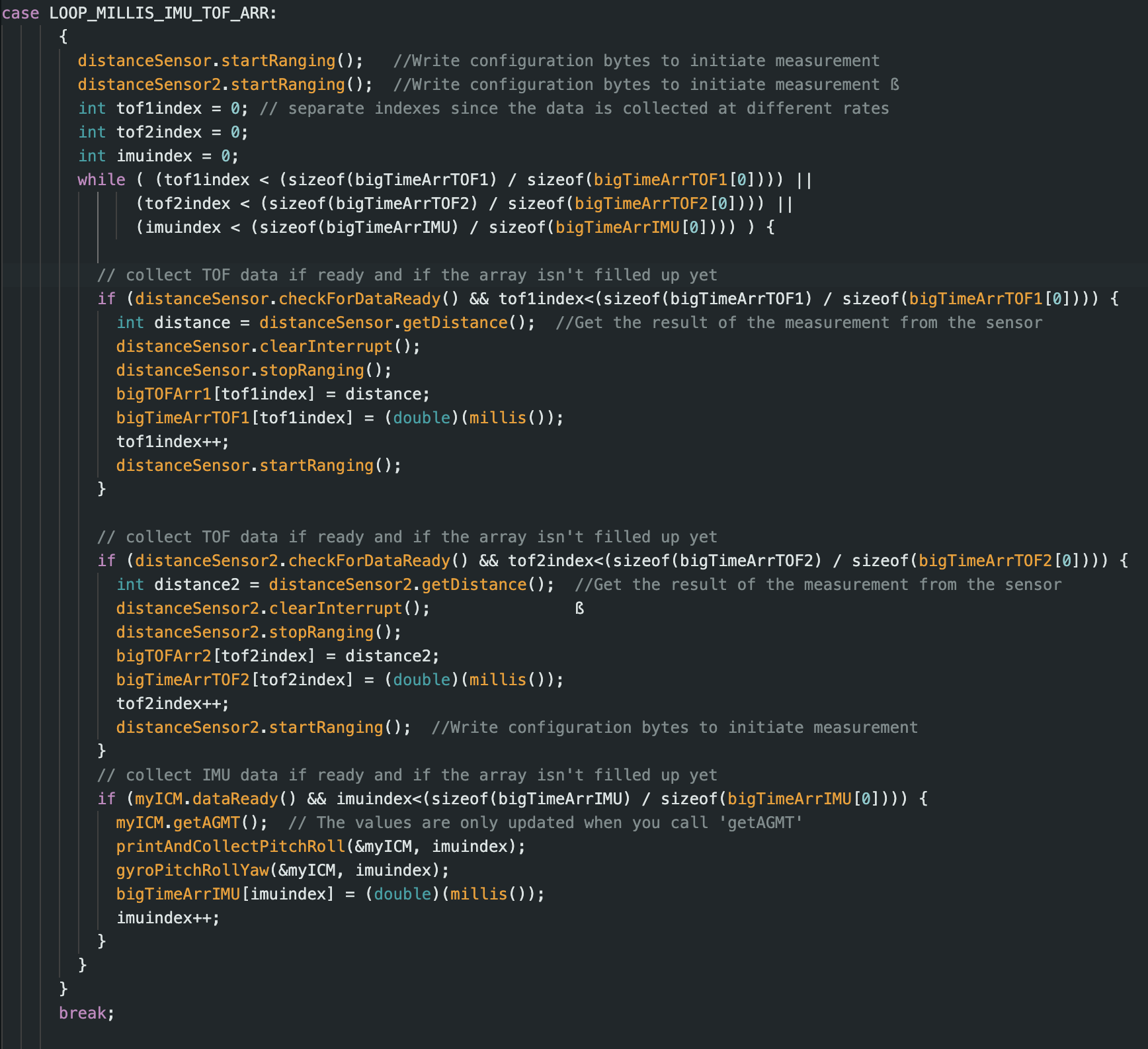
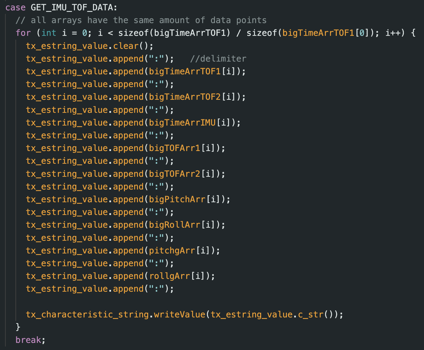
My Arduino script to collect both the TOF data and IMU data is shown below. Similar to previous labs, one command collects the data, while the other command will relay the data via BLE to my computer and use “:” delimiters to separate the data. I have a time array for each of the three sensors because they all collect data at separate rates. Even though the two TOF sensors should gather data at the same time, there might be a slight delay since it isn’t truly parallel, so I have two separate time arrays between these two data sets to be the most truthful. In one iteration of the loop I first collect the distance data from both sensors (if available) and then the IMU data (if available). If any data isn’t available, I won’t halt the loop and cause it to hang until the data is available, so another sensor that is available can log its data. This is important because, as discussed before, the IMU reads faster than the TOF, and we don’t want to be holding the IMU data up. Once all arrays fill up to their requested data amount, we stop collecting data. I collected 400 data points from each of the three sensors. For future labs, I can continue gathering more IMU data as we collect TOF data since the IMU data collection is faster than that of the TOF data collection rate.
Collaborations
I would like to thank Prof. Helbling and TA Julie for their help in lab and quick responses on ed. I referenced Aidan McNay's, Aidan Derocher's and Stephan Wagner's webpages from previous semesters. Generative AI was used in lab for helping understand the lab handout and helping code to this website. This website template was also inspired by Hunter.