Prelab
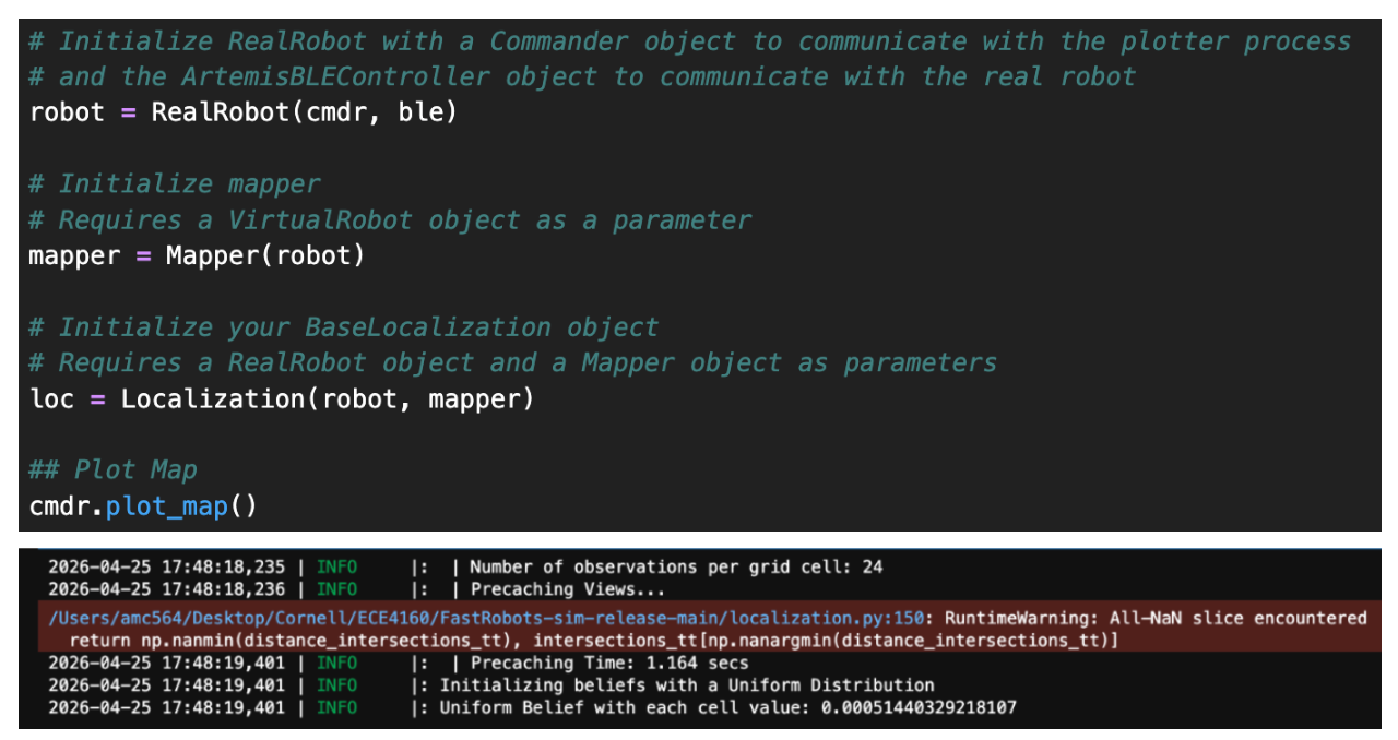
We are provided an optimized implementation of the Bayes filter. I followed the setup instructions. The time the optimized implementation takes to run is 0.011s and 0.001s for the prediction and update time, respectively, which is faster than my implementation from the last lab.
Tasks
Simulation
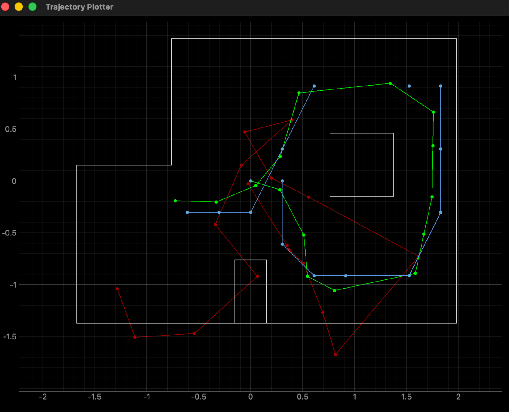
I ran the lab11_sim.ipynb notebook, and below is the simulation plot with odometry(red), ground truth(green), and belief(blue).
Perform_observation_loop
Here we command the robot to do a 360° in-place turn counterclockwise, stopping every 15° to collect TOF data. 0° starts at the robot's current heading and is where data will be first collected. We return "sensor_ranges," which is a column NumPy array of the average TOF range values (meters) measured at each 15° increment. I changed word.yaml’s “observations_count” to be 24 since we are measuring every 15°. By taking more measurements, we increase the accuracy of our localized pose.

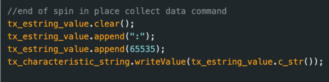
First, I modified my lab 9 Arduino script where the robot went CW and collected TOF data at 15° increments. Here we must go CCW, as seen below.
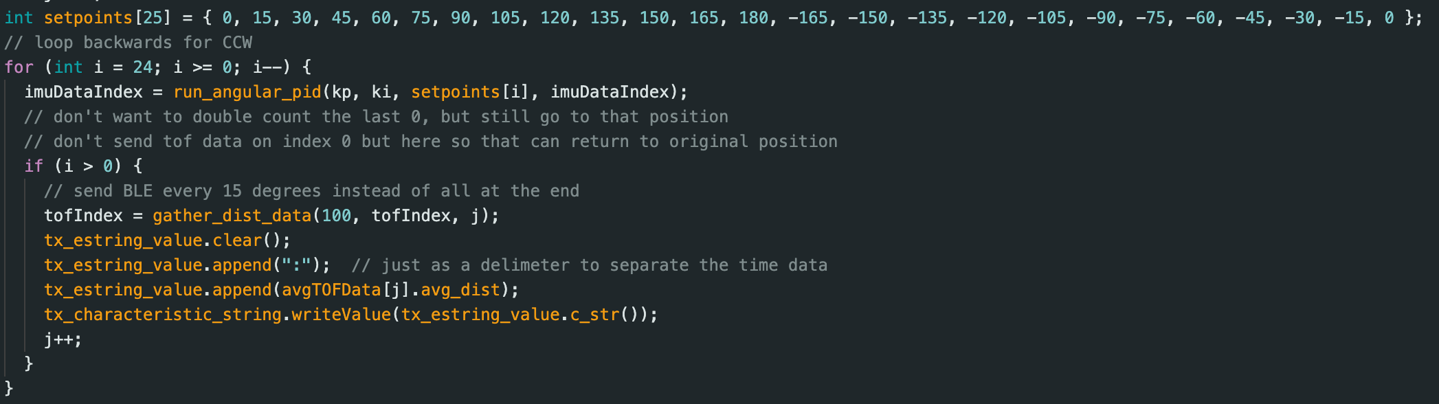
I now take averages in Arduino. One bug I had that led to weird errors was I had total_dist as a uint16_t instead of a float, so when I added up all 100 TOF measurements, it would sometimes overflow and wrap around, causing unexpected behavior.

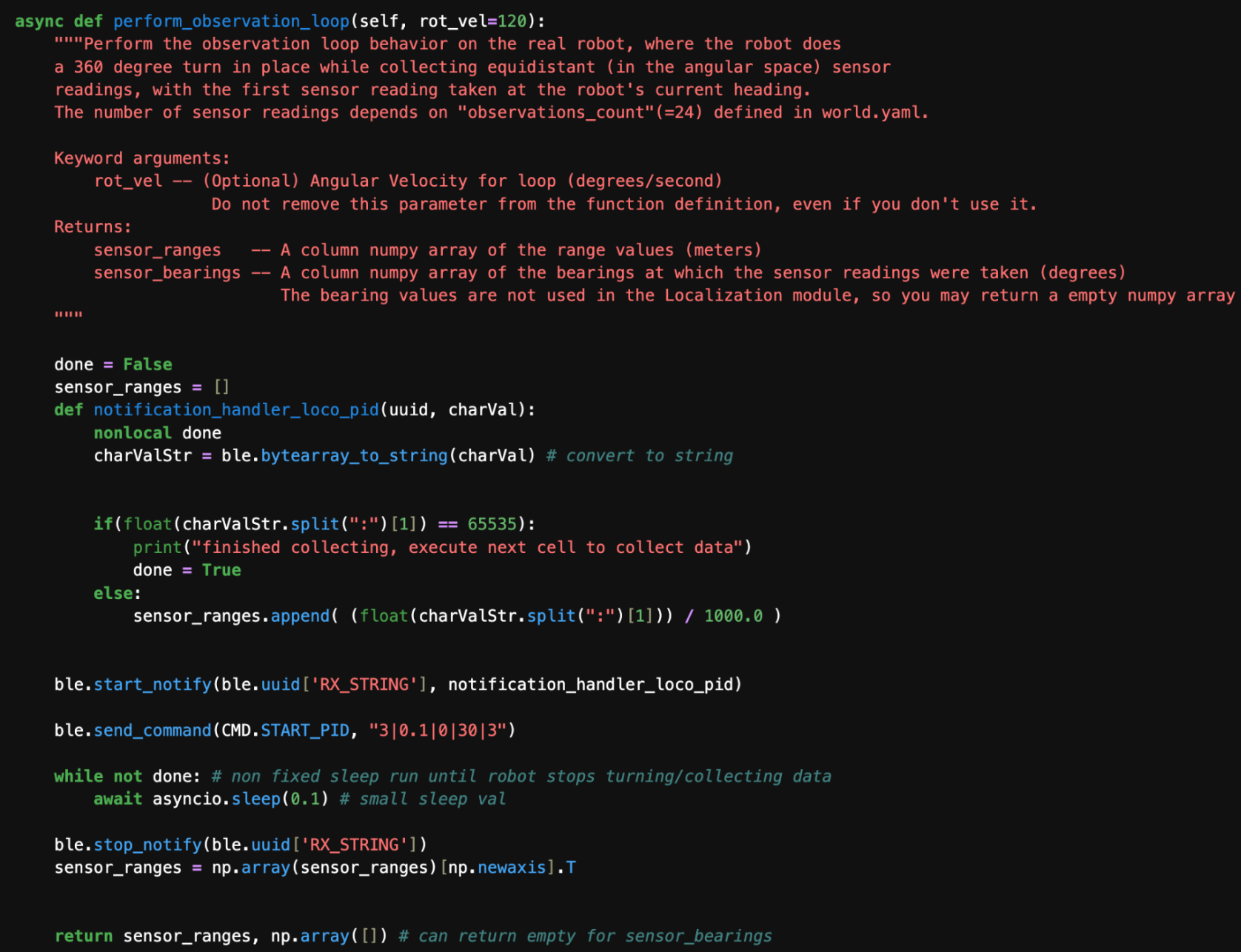
In “perform_observation loop," I will call asyncio coroutines (namely, await asyncio.sleep(0.1)) as I will use BLE handlers to collect TOF data from my robot as it spins. I add the “async” keyword to the definition of "RealRobot.perform_observation_loop."

In lines 311-313 of localization.py, I add “async” to the function definition and “await” when I call the async coroutine "perform_observation_loop(rot_vel)."

I also put “await” in front of “loc.get_observation_data()”
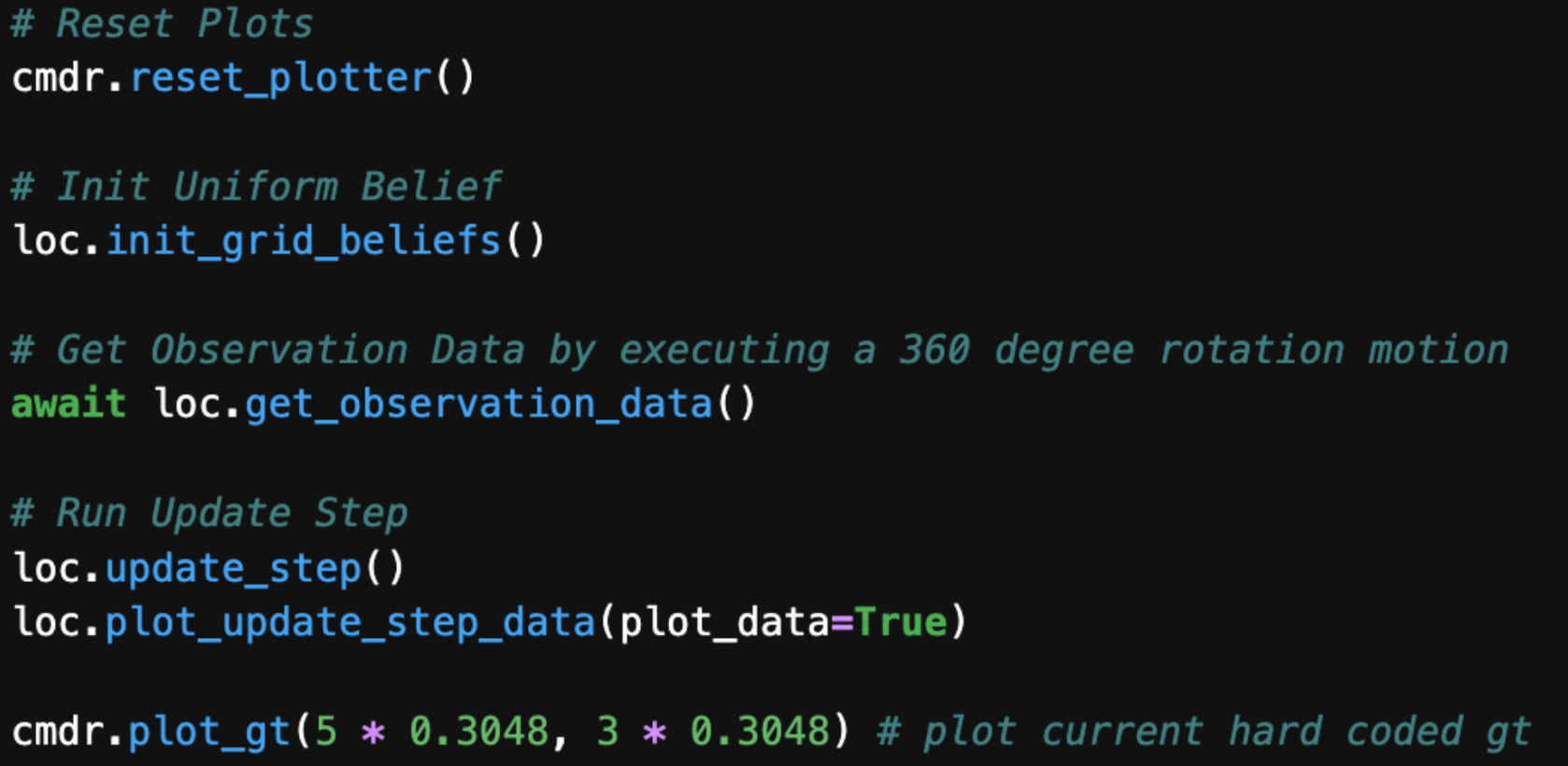
Now, to implement perform_observation_loop, I define a notification handler inside this function as seen in previous labs.
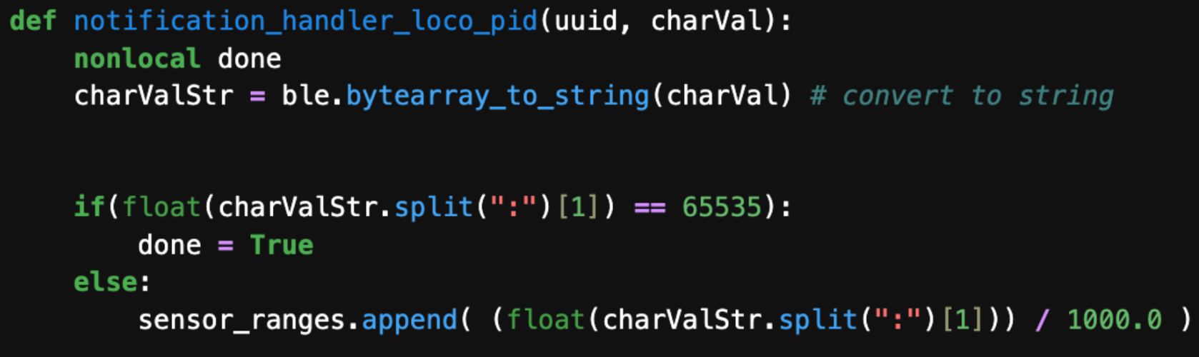
It collects TOF data sent over from the MCU over BLE and appends it to a list (while also converting it from mm to m). When the MCU sends "65535," as seen below, that means we are done collecting data, and we can set the “done” flag to true. The “done” flag is not global, but local to the “perform_observation_loop” scope.

Full code:
Results
At ((-3ft,-2ft,0deg),(0ft,3ft,0deg),(5ft,-3ft,0deg),(5ft,3ft,0deg)), we run the update step not prediction step, as the robot’s motion is pretty noisy, so it won’t help that much. I execute the following cell to have a uniform prior on the initial pose.
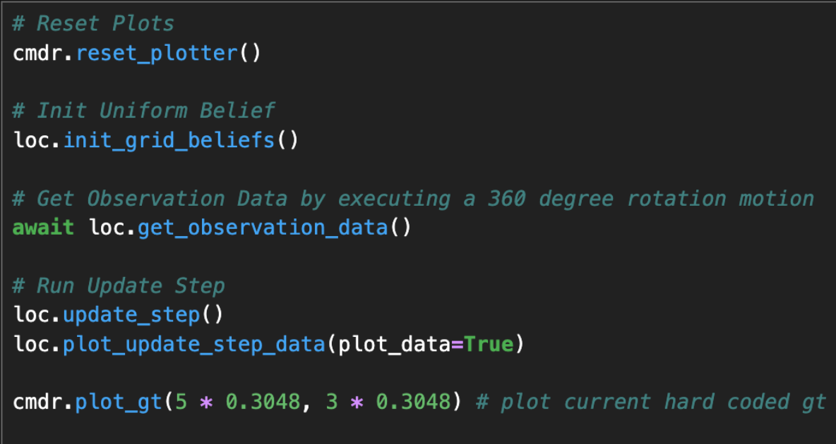
I run the following cell to execute the observation loop and only the update step on my collected TOF data. I plot the belief(blue) and ground truth(green).
Example Loop
(-3ft,-2ft,0°)
The front of the robot points in the +x direction (0°).
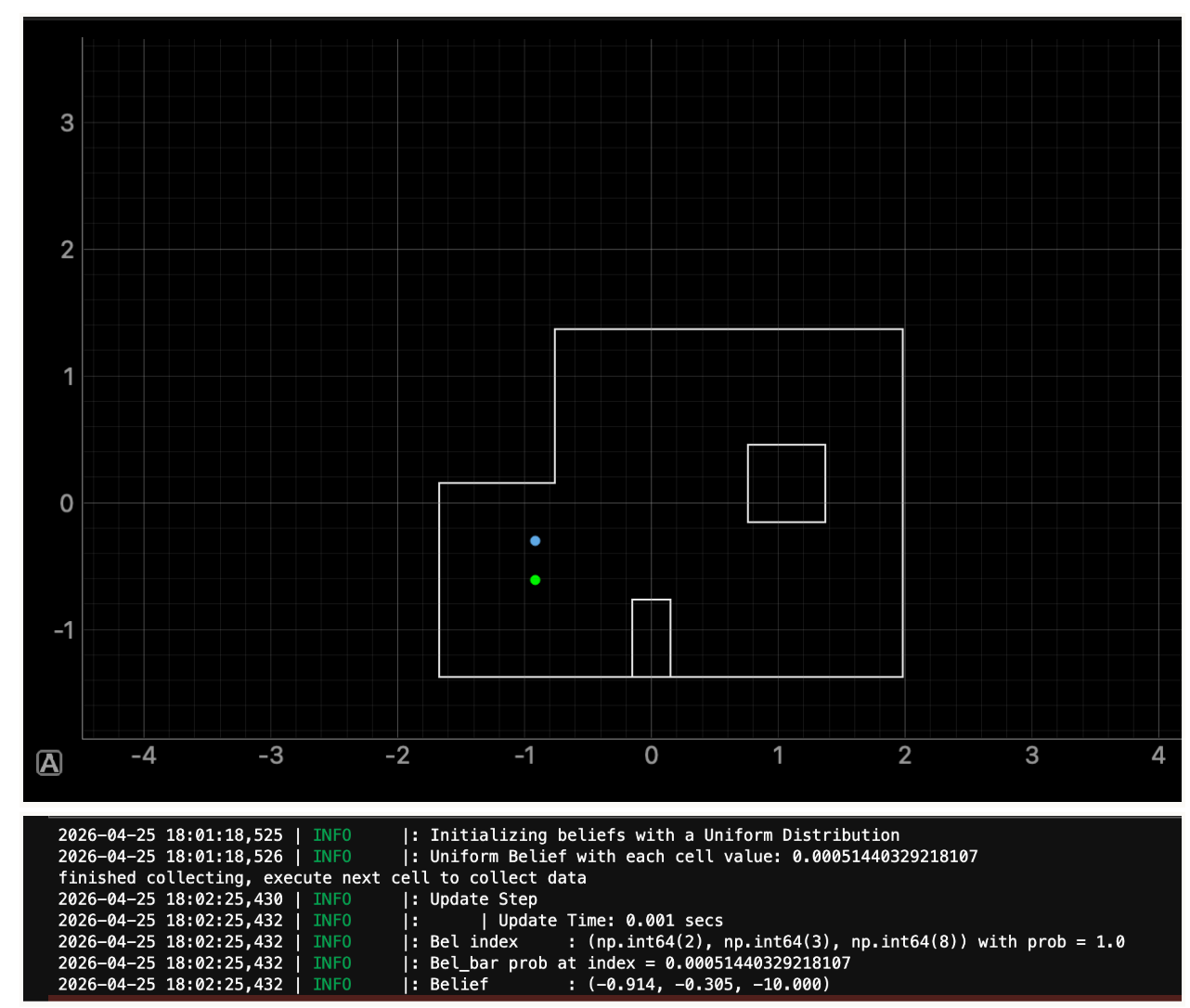
There was some error in the +y direction, so I redid this point with the front of the robot now pointing in the +y direction initially.
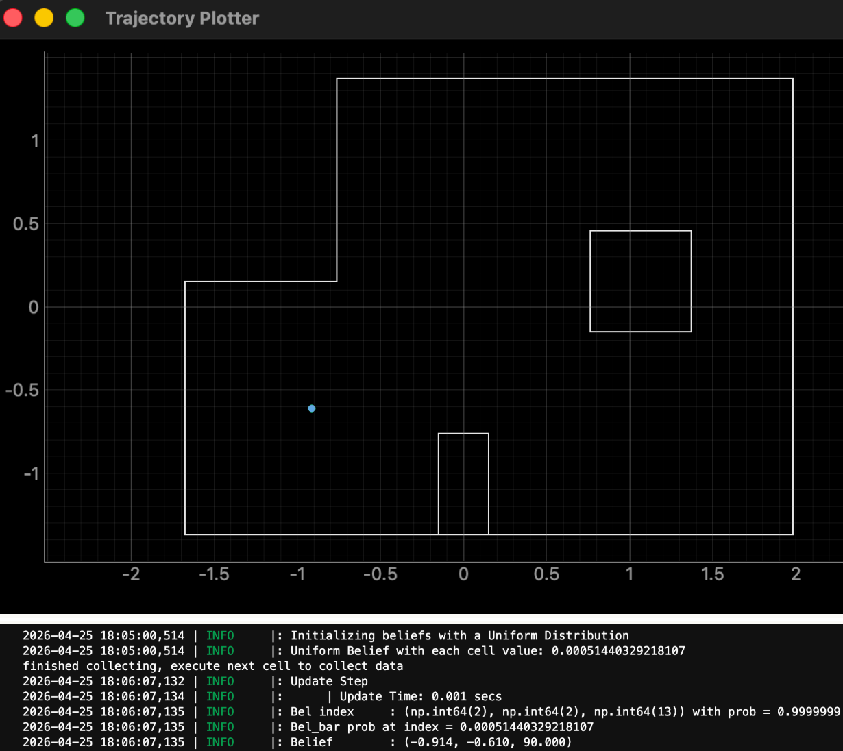
This is spot on. The belief is accurate in theta at 90° (we are pointing in the +y direction). At 0°, the robot sees the wall furthest to the right, which is close to 3m away (the max distance the long mode of the TOF can read). If the object is out of range, the TOF will output 3m even if it truly isn’t that distance. The Bayes filter does not know about this since it assumes a linear sensor model. We could adapt the implementation to handle nonlinear sensor models, but we do not need to for this lab. Instead, we orient the robot initially at 90° so that the TOF points at a wall that we can guarantee its measurement (<3m away).
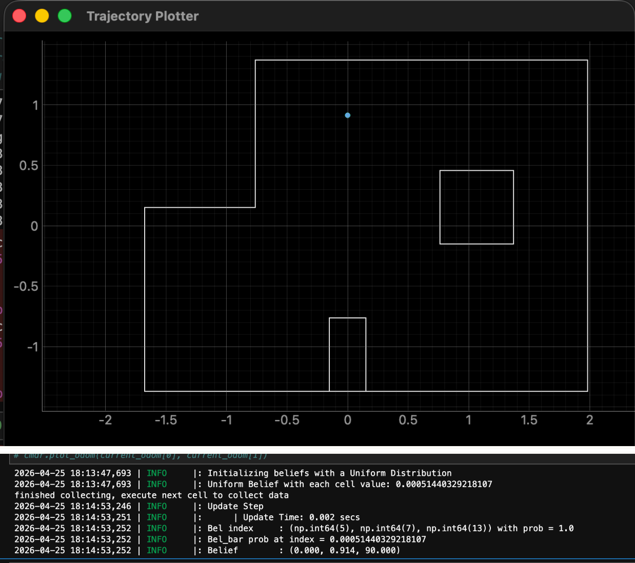
(0ft,3ft,90°)
Due to the success of the last trial, I once again place the robot at 90° initially.
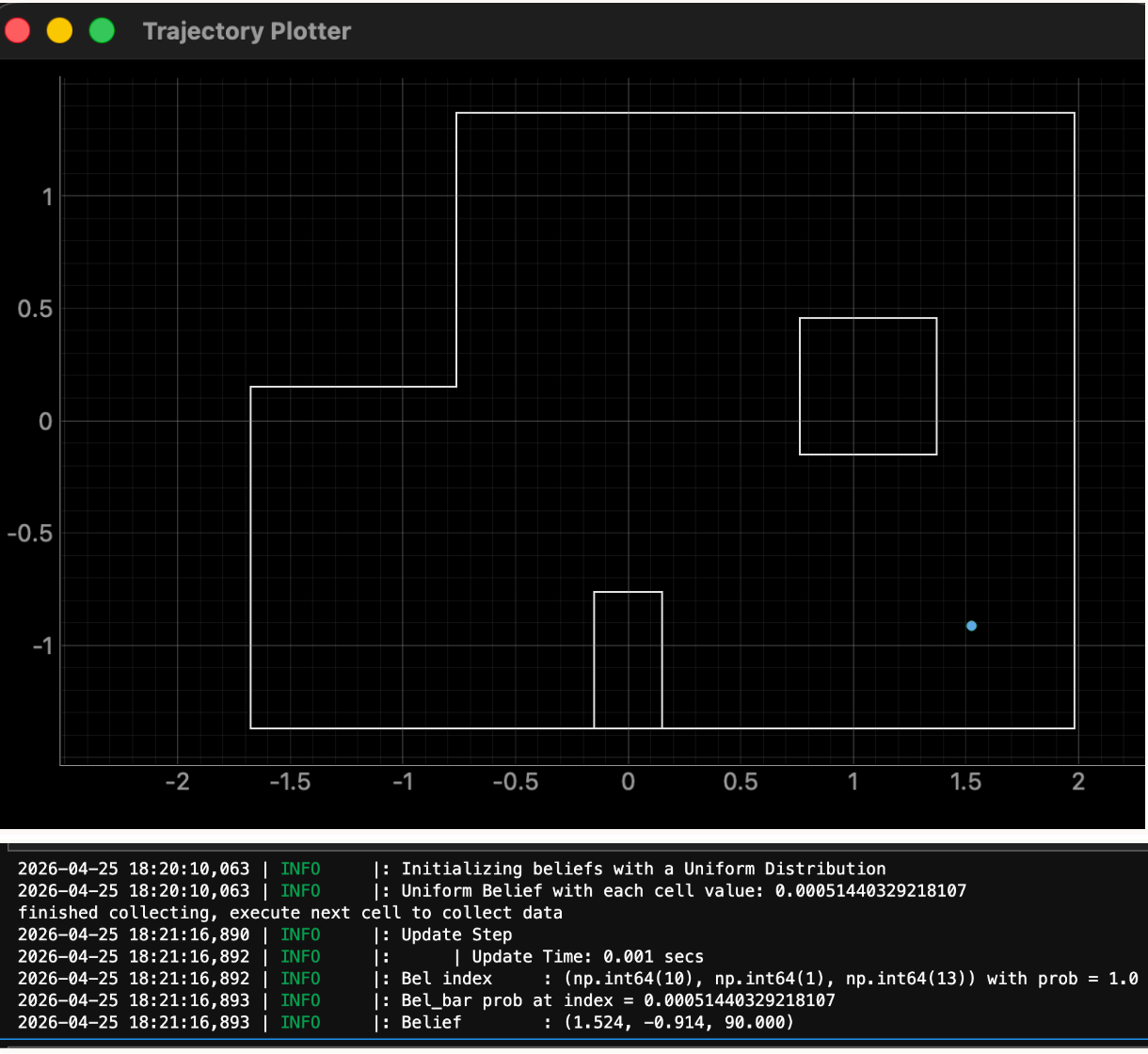
(5ft,-3ft,90°)
(5ft,3ft,90°)
Initially I tried 90° again, but I had noticeable errors in the x and y directions and theta (70° instead of 90°).
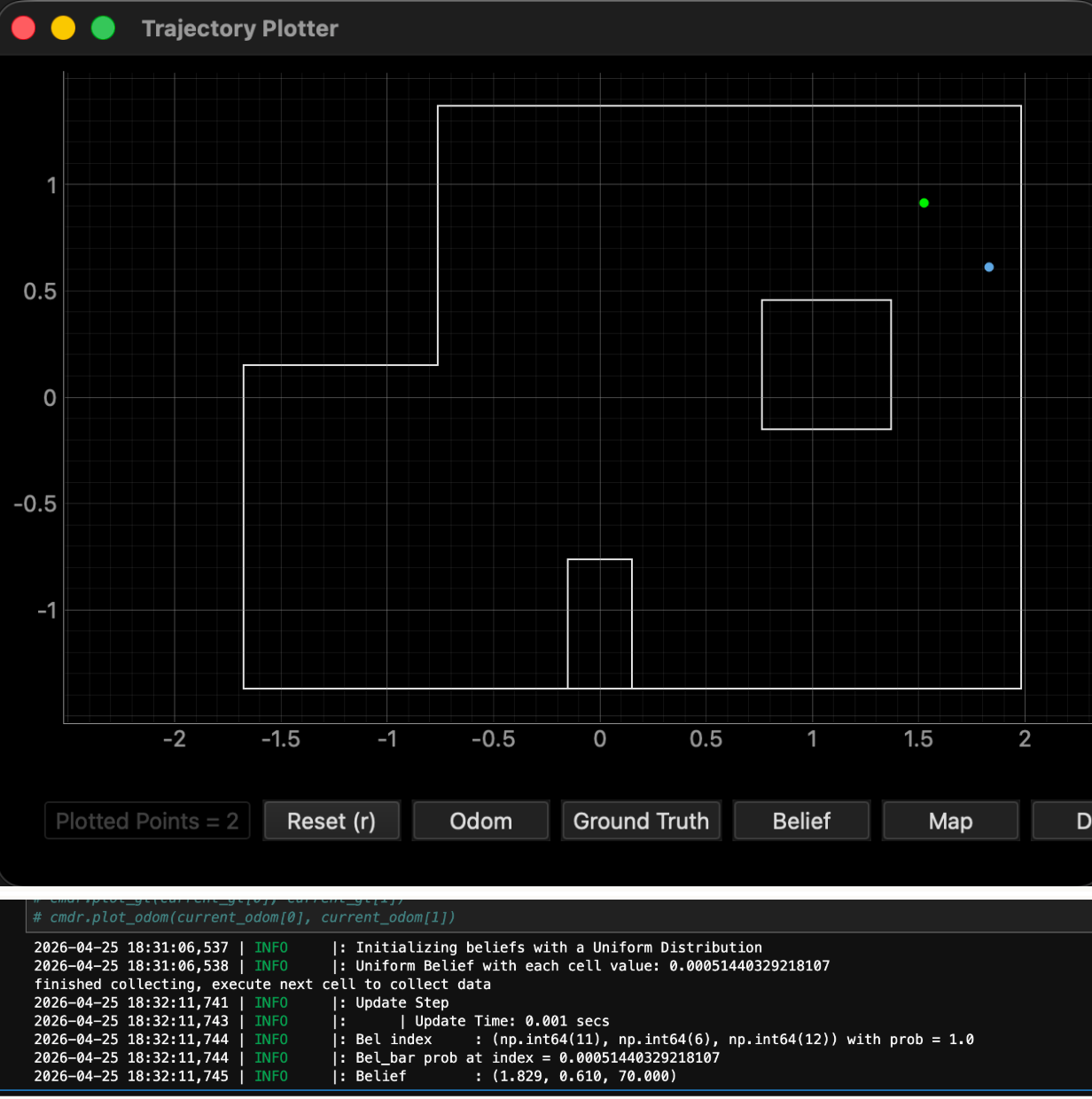
Here, starting at 90° is bad since the top wall is very close and may not get accurate readings. I chose to start around -45° to get the most of the right wall and then the top wall. This was more accurate (only error in the theta and y direction).
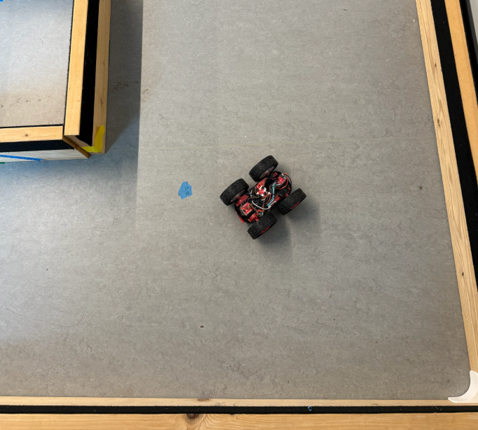
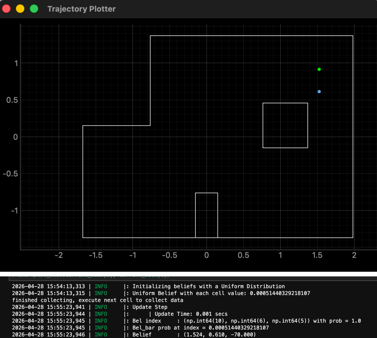
Additional point (-1ft,3.5ft,90°)
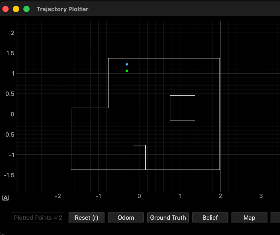
This is the same issue as above.
Additional point (-4ft,-1ft,90°)
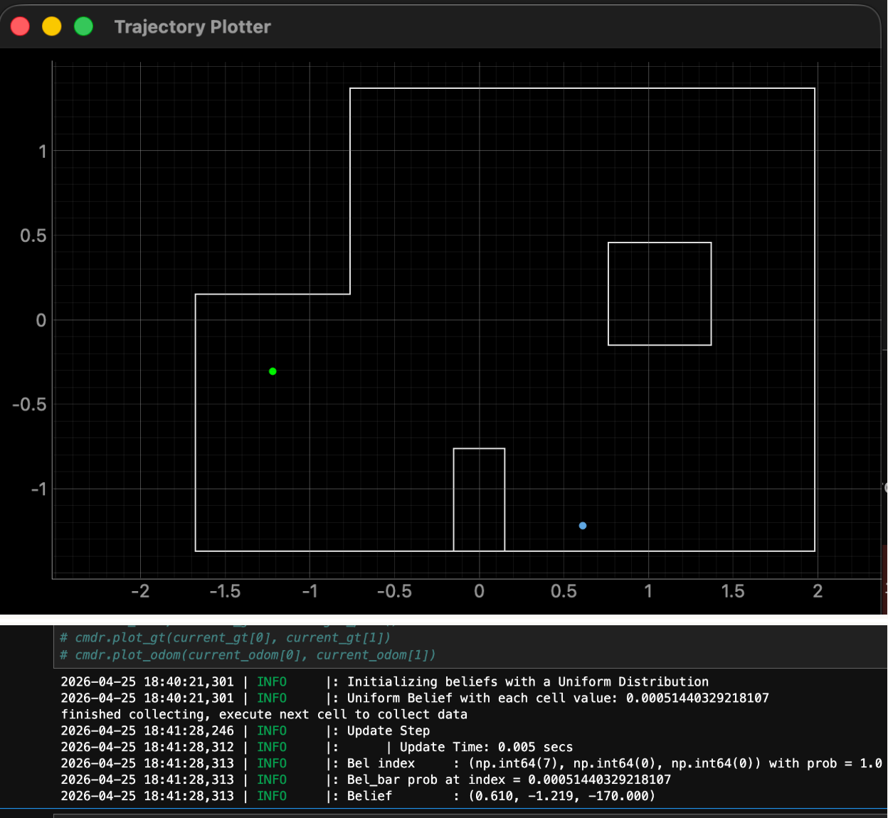
I got this waypoint from Jack Long. The xy directions and theta are way off.
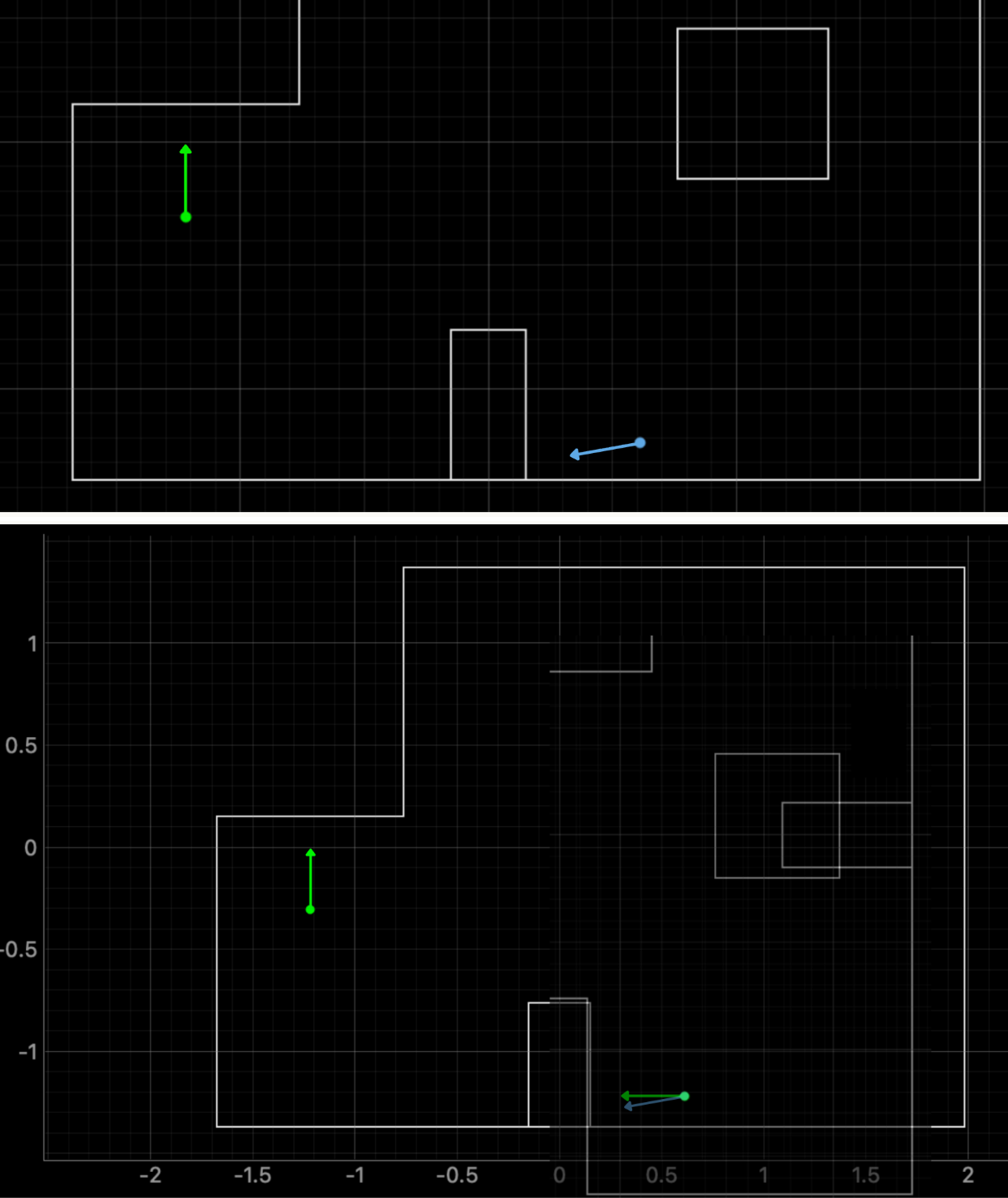
I took the ground truth and rotated it to -180° and overlaid it with the belief so you could see how some features of the map look the same at different waypoints but in different orientations. This could be a plausible reason for the y-direction error for the point (5ft,3ft). When we do path planning, we might want to reintroduce the prediction step so if we jump very far suddenly/impossibly, we put less belief in those points. Without the prediction step, the robot can “jump” anywhere.
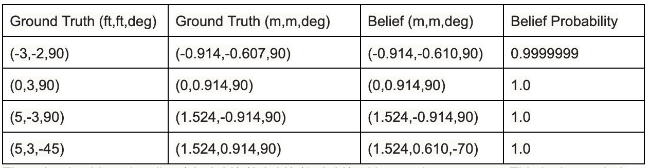
The robot can localize (-3,-2,90),(0,3,90),(5,-3,90) with accuracy because of their geometric distinctiveness. These points cannot be mistaken for a different part of the map. The only inaccurate point was (5,3,0). As discussed above, other waypoints on the map have similar geometric surrounding structures, just at a different angle, which explains the error in the xy direction and angle. We only do the update step. The belief probability is due to rounding and normalization and does’nt mean there is a 100% chance of being in that localized point. (-3,-2,90) is off in the y-direction by 0.003m, and (5,3,-45) is off in the y-direction by 0.304m. The 0.003m error is most likely due to rounding since the granularity of the grid cell is 0.3048m. (5,3,-45) is only off by a grid cell. This is also why the other 3 points seem very accurate; it is because we are at the granularity of grid cells (0.3048m,0.3048m,20°), so it is more “accurate” than we think.
Collaborations
Thank you Prof. Helbling. I referenced Aidan McNay's, Stephan Wagner's, Jack Long's websites. Hunter inspired this website template.