Lab 1A
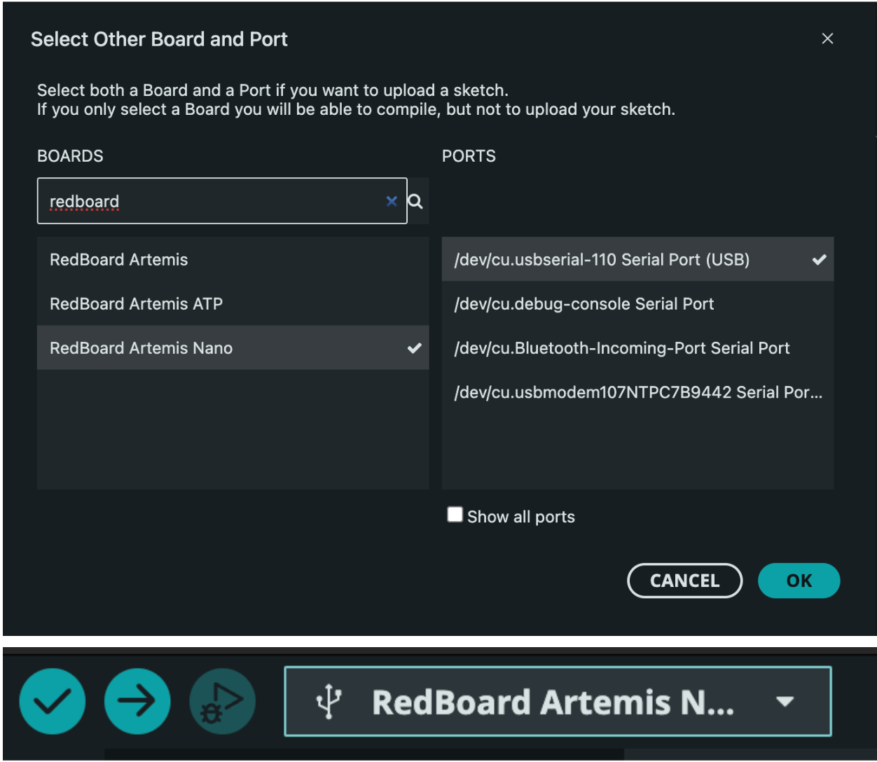
To warm up for lab 1, I set up the Arduino IDE and the Artemis board so that I am comfortable with how they work before proceeding with harder tasks. I now know how to program the MCU and went through example scripts for us on the onboard LED, communicating via UART over USB to display content on the serial monitor based on data received from the MCU from sensors like the temperature sensor and microphone on the MCU. This will be discussed in more detail below. When uploading code to the MCU, I ensure a good connection and ensure the name of the board and port are correct.
Blink
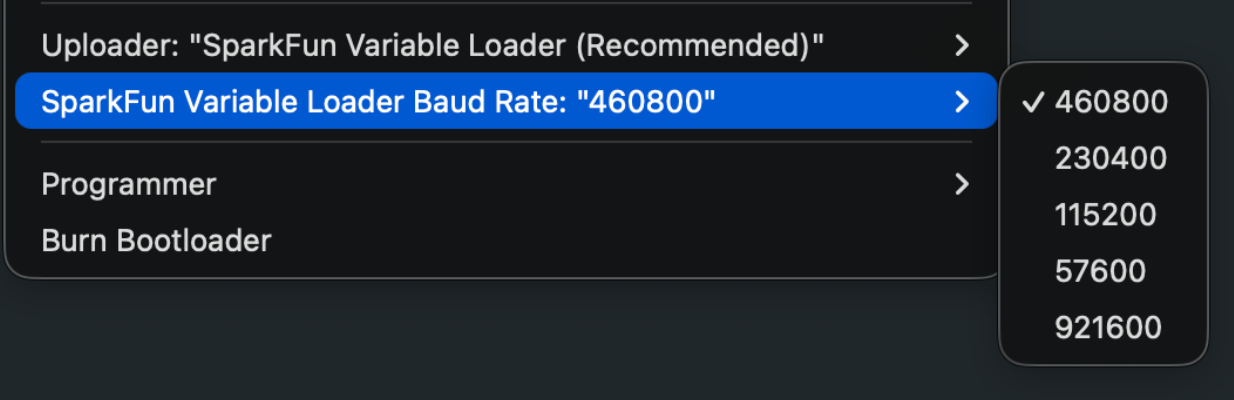
I could upload the code at the highest baud rate so I will be able to upload code to the MCU as fast as I can. Some students in the past have had issues with this and had to lower this baud rate.
Below is a video of the code running where you can see the onboard led blinking on and off. This is practically the “Hello World!” microcontrollers!
Serial
I ensured the baud rate of the serial monitor was correctly set to 115200 and then uploaded the code. Some text is printed to the serial monitor and I can also write to the serial monitor and the code will echo it back out to the serial monitor as seen in the video.
Analog Read
This code measures and reads out to the serial monitor a bunch of analog values, namely the raw ADC counts from the temperature sensor on board the MCU. You can see a demo of this in the video below.
Microphone
This code collects data from the on board microphone and will output the frequency on the serial monitor as seen in the video below.
Lab 1B
Prelab - Setup
The main goal of this lab was to make sure the MCU and my computer could communicate via the bluetooth stack so for later labs I have a way to communicate with my robot and collect and parse data from it. We can send commands and data back and forth between the MCU and my computer. The MCU has Arudino code on it while my computer has python code on it in a Jupyter notebook.
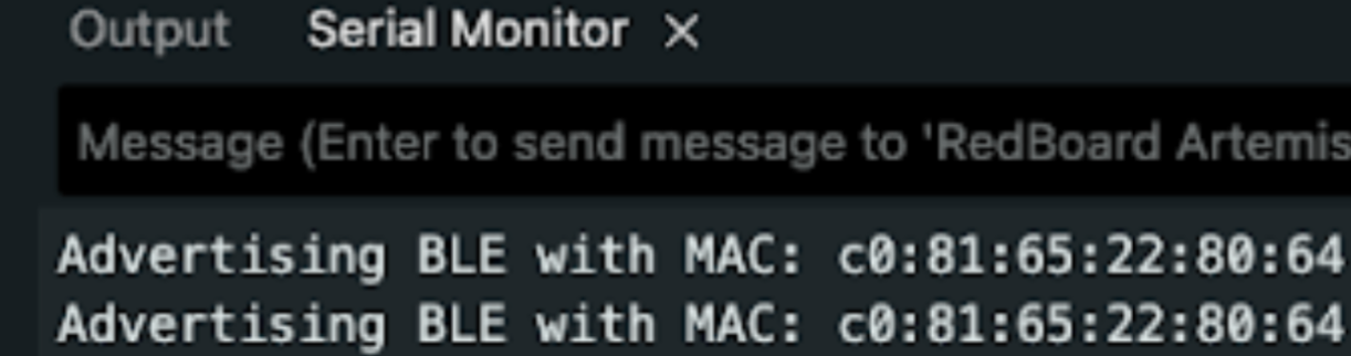
I first installed python 3.13 with pyenv so I can easily switch between different versions for other classes besides this one. I then set up a virtual environment named “FastRobtos_ble”, activated it, installed all proper python backages and then started to look at the codebase. I will discuss the codebase more later, but I burnt the ble_arduino.ino sketch onto the MCU to get its MAC address as seen below.
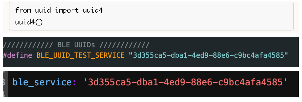
This MAC address is then updated in the connections.yaml file in the code base so the MCU and computer can agree. Then I changed the BLEService UUID to make my board unique from the other boards in the class. I use the code below to generate a unique new UUID (the chances of overlapping with another student are nearly impossible). I update this value in both the Arduino and connections.yaml file.
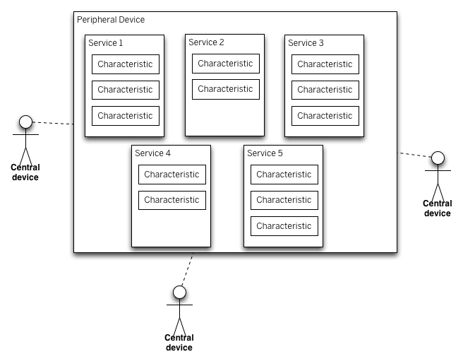
The code base consists of scripts for the Arduino and Python side of things. The Arduino side is where we define the commands that the Python script calls and also has all the header files that act as class definitions. The Python side also has Bluetooth information in the connections.yaml file and cmd_types.py are used to assign a number to all the enum values that are used for the switch statements in the Arduino file to decide which command we are running. The Python side is where we execute commands. We can send and receive data from either the Arduino or Python side, but it would make the most sense to collect and send data from the MCU using GATT characteristics and parse and analyze that data on the computer. Instead of reading the data directly, we can use a callback function to "catch" the string and parse and handle it from there. The MCU acts as the peripheral, and the computer acts as the central device, as seen in the image below. They communicate via BLE.
Task 1: Echo
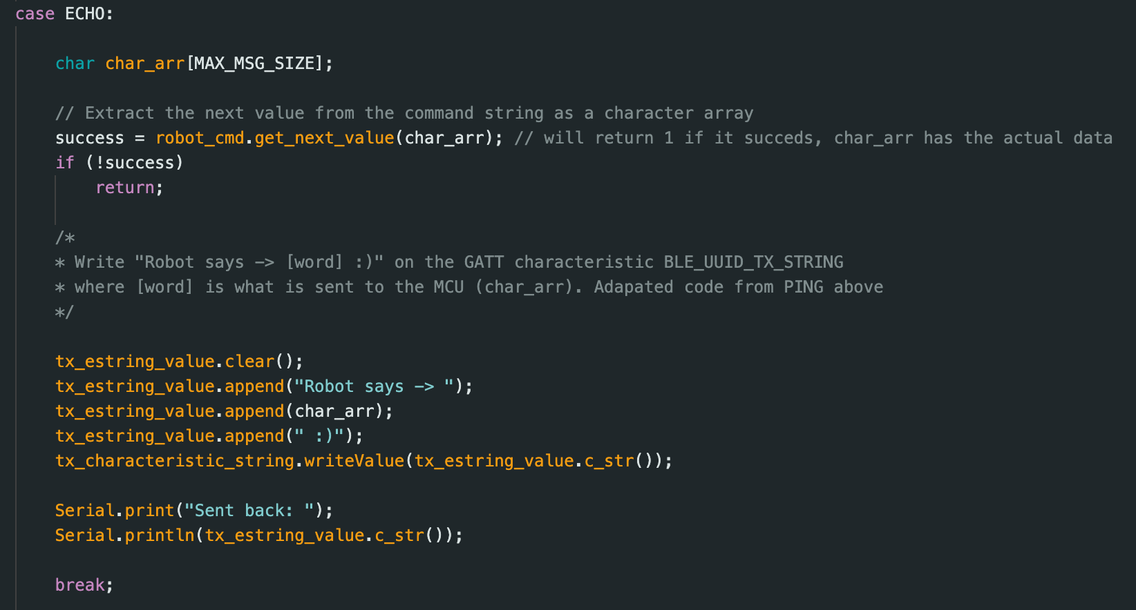
I send a string value, “what’s up gang,” from my computer to the MCU with the ECHO command. Once the MCU receives this string value, it will echo back to the computer “Robot says -> what’s up gang :),” which the computer will print out from a GATT characteristic it reads.
Code snippet below for ECHO command in Arduino:
Task 2: Three Floats
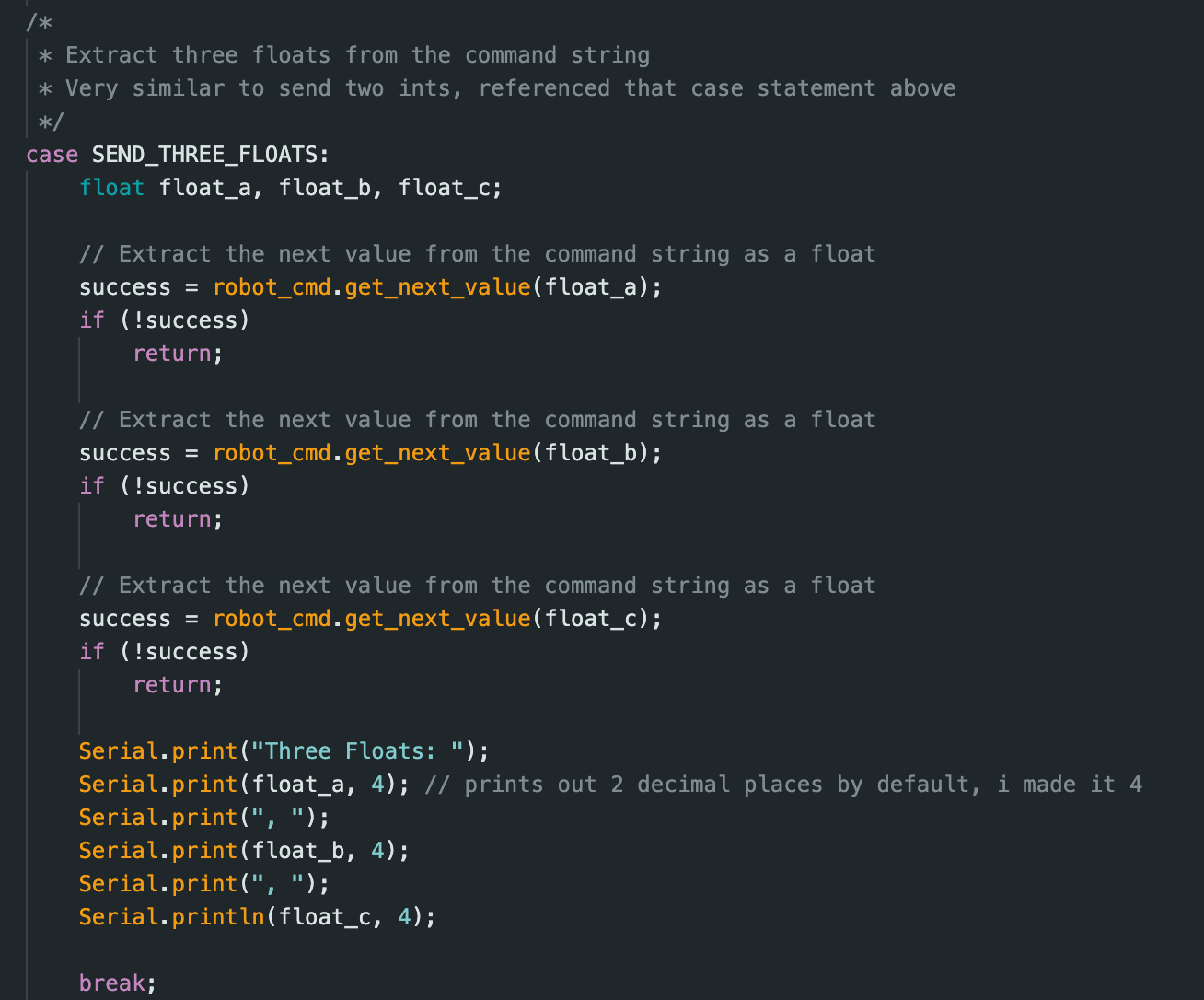
I created a SEND_THREE_FLOATS command in Arduino and ran this command in Jupyter Notebook with 3 float values. As seen in the video, the three float values were received by the MCU and were extracted and displayed in the serial monitor.
Code snippet below for SEND_THREE_FLOATS command in Arduino:
Task 3: Get time in milliseconds
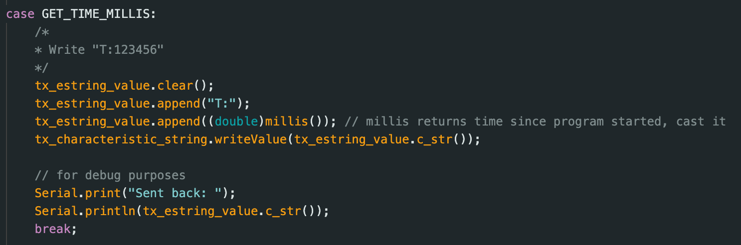
For this task I created a GET_TIME_MILLIS command that tells the robot to send back a string formatted as “T:current time,” where current time is the time since the Arduino script started running in milliseconds. The Jupyter notebook will parse this string and print it out in the output of the notebook as seen in the video.
Code snippet below for GET_TIME_MILLIS command in Arduino:
Task 4: Notification Recieve String Time
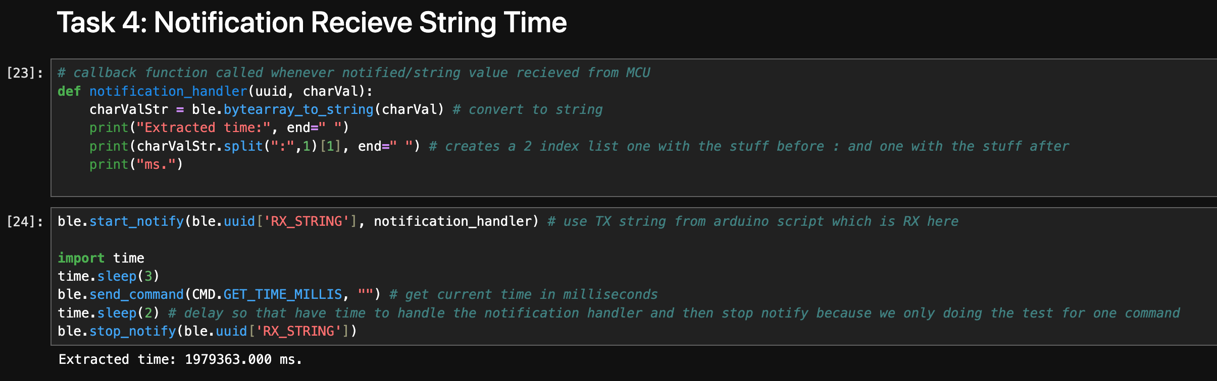
This part is mainly done in the Jupyter notebook, where I define a callback function to extract the current time from the string that the computer has received from the MCU. When we call the GET_TIME_MILLIS command, the MCU will send a string with the time to the computer, and the notification handler will receive this string, which is also the BLEStringCharactersitc from the Arduino. In the callback function we must convert the byte array to a string and then use the “:” delimiter to get the actual time value from the “T:current time.” More details are discussed in the video below:
Code snippet below for call back function and start and stopping the notification handler in python:
Task 5: Loop current time
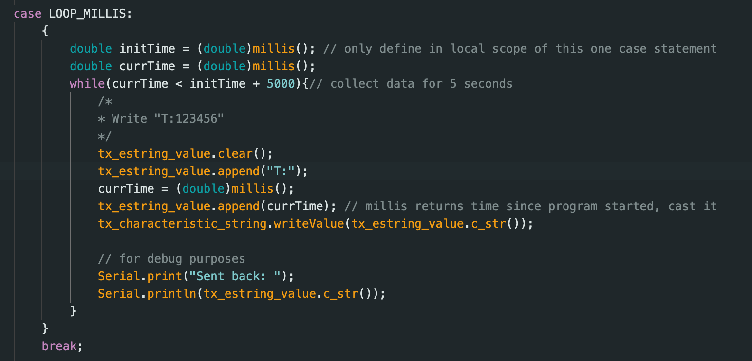
I created a command called LOOP_MILLIS, which essentially does the same thing as GET_TIME_MILLIS but does this over and over again for 5 seconds. I use a while loop that knows the initial time this command is called, and it just keeps gathering time data and sending it to the computer for 5 seconds. Each iteration of the loop a string is sent out, which the notification handler processes, and then we print out all the time stamps to see the speed messages can be sent.
Code snippet below for LOOP_MILLIS command in Arduino:
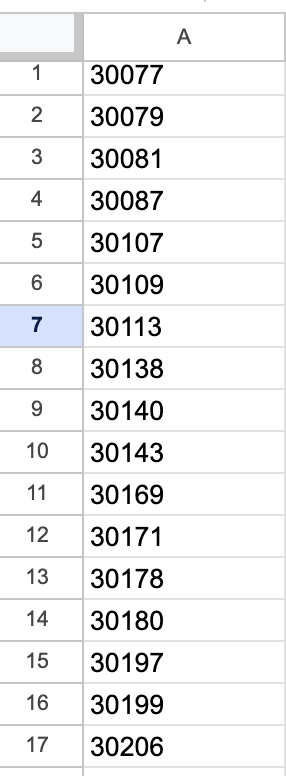
Each time we send the time data, it is sent as a byte array. When calculating the effective data transfer rate of this method, the data took the form of “T:31013.000,” which is 11 bytes. I took 69 data points that lasted 0.936 seconds, and the effective data transfer rate is total data/total time = 11*69B/0.936s = 810.897 B/s on average. Below is a screenshot of the Excel sheet of my data.
Task 6: New Method of Collecting Data First
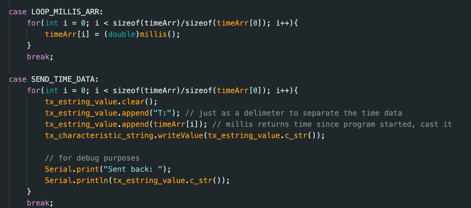
In this task I test a new data transfer method where I collect time data for 100 iterations and send nothing over Bluetooth. Afterwards I set up the new notification handler and then executed a new command, SEND_TIME_DATA, which loops this global time data array and sends each element of the array as a string to the computer to be processed and put in a list in the Python script.
Code snippet below for LOOP_MILLIS_ARR and SEND_TIME_DATA command in Arduino:
Task 7: New Method with Also Collecting Temperature Data
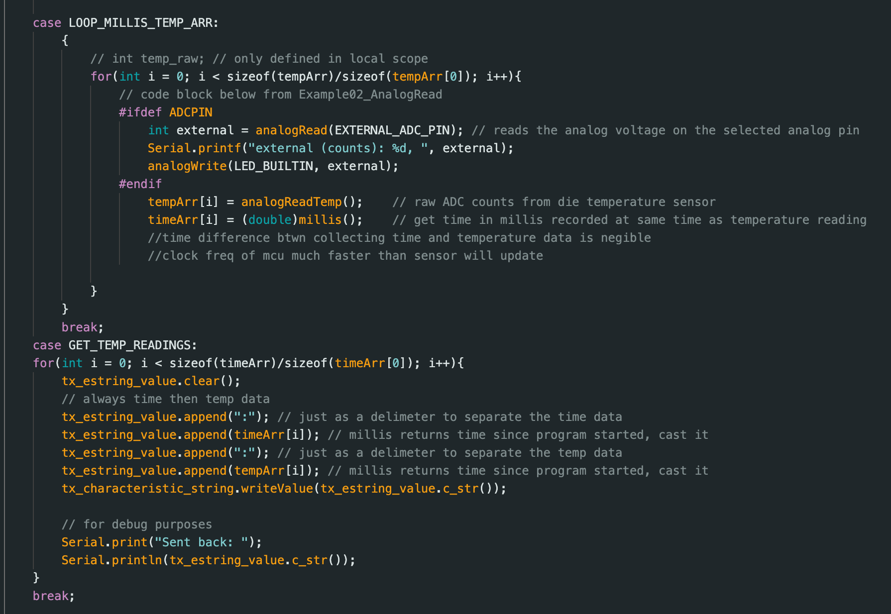
This task is very similar to task 7, but now in the same iteration of the loop we are also collecting temperature data in LOOP_MILLIS_TEMP_ARR by adapting a function from lab 1A, and we are sending temperature data in the same iteration in GET_TEMP_READINGS. We need a new modified notification handler/callback function to handle these two readings. Then I print out the two separate time and temperature lists. The time and temperature data are technically not collected and sent out concurrently, but the time difference is so negligible compared to the Bluetooth delay that colloquially we can say it is concurrent.
Code snippet below for LOOP_MILLIS_TEMP_ARR and GET_TEMP_READINGS command in Arduino:
Task 8: Difference in methods
In this lab we tested two different methods. The first method is sending the data from the MCU to the computer every iteration of the loop, and the second method is collecting the data in an array and then, after collecting all the data, going through this array and sending data in an array. The advantage of the first method is that we don’t have to wait for all the data to be sent over at once. We keep getting data updates after each iteration of the data collection loop. If we take in one data point each iteration, then we only have to wait for that one data point. The disadvantage is that it is slower due to the Bluetooth delay. The first method is best, for example, when you are monitoring the temperature of an oven, you want to lower or raise the heat based on the internal temperature, so if there is a change in the next data point, you want to change the heat output right away. There may be some delay, but this is ok because it takes a while to change the temperature anyways.
The second method is good because then the data isn’t slowed down by the Bluetooth when collecting the data, and then we can get data closer together in time (notice how in task 6 the timestamps are basically all the same values instead of the big jumps seen in task 5). You would choose this method for time-sensitive data, like if you wanted to track the speed of an object in a short amount of time. If you do not do the array method, you will not be fast enough to collect enough data points because the Bluetooth delay will make you miss the timing deadlines. The main disadvantage is running out of memory. The Artemis board has 384 kB of RAM, and if we only consider time data from task 5, that is around 11 B per data point (it will increase as time goes on because it is a byte array, not an integer), so we can store around 384 kB/11 B = 34,909 time data points without running out of memory. Note that some of the RAM is probably already used up by the program. From the picture below (output from compiling the Arduino script), there are 361240 bytes for local variables, so really we only have space for 361240/11=32840 data points.
For task 6, the effective data transfer rate is (11*100)B/2ms since it took 2ms to collect 100 data points of 11B in size, so 550kB/s, which is how “quickly” the second method can record data.
Discussion
I learned the command of the case statement must match the name and be in the same order in the Python and Arduino scripts. Most of the challenges I faced were from overthinking what the lab was asking, but I was able to clarify my questions in lab and on Ed. I briefly learned about Bluetooth stacks in ECE 4760, but this is my first time getting hands-on experience with them. Other issues I faced were the code not working because I forgot to connect the Bluetooth to the MCU and also forgetting to stop notifying before trying to start notifying again. I also learned that saving the data in an array and then sending it over Bluetooth from the MCU to the computer is better than sending it one data element at a time because you would much rather the delay be between big collections of data, especially time-sensitive data. Also, when sending these big collections of data, there will be a delay as you send element by element of the array, but during this time you can collect more data possibly.
Collaborations
I would like to thank Prof. Helbling and TA Julie for their help in lab and quick responses on ed. I referenced Aidan McNay's and Aidan Derocher's webpages from previous semesters. Generative AI was used in lab for helping understand the lab handout, refreshing on python syntax, and helping code to this website. This website template was also inspired by Hunter.